SVC 6-5
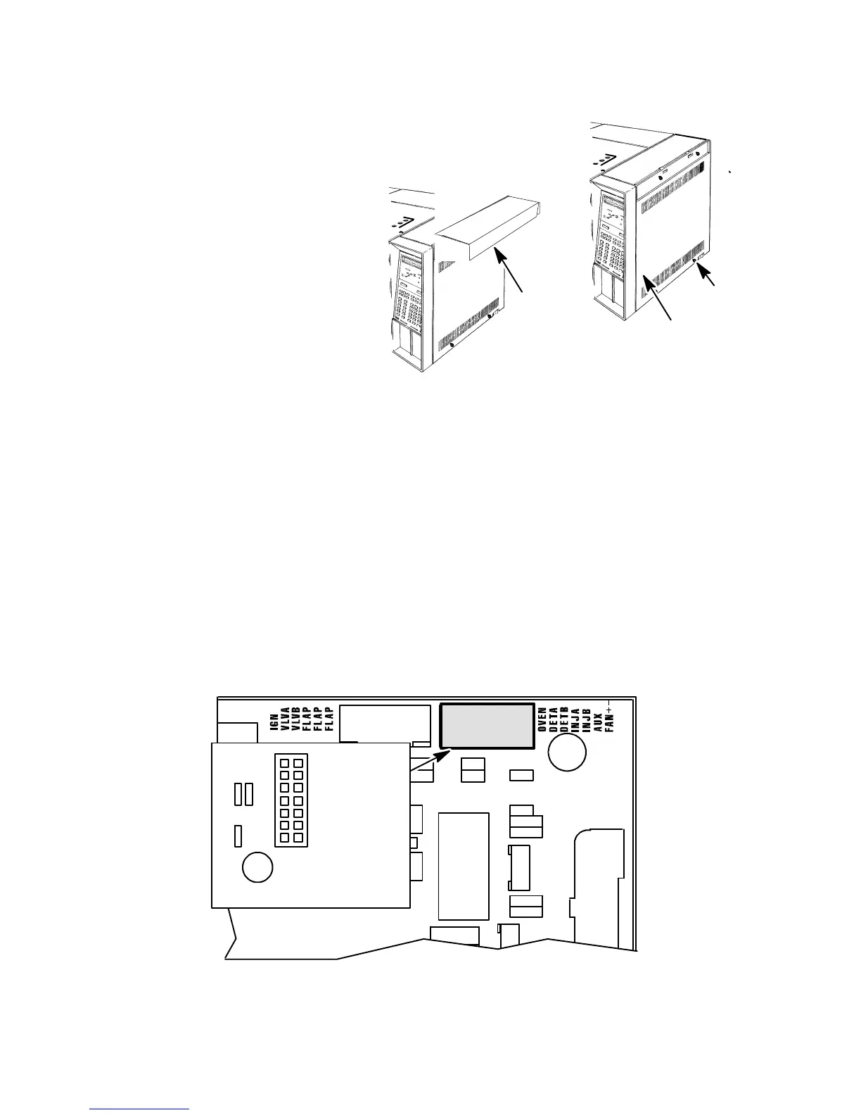
6. Remove the electronics carrier top cover by
grasping it at the rear and lifting until its catch
releases, the pulling it toward the rear of the
instrument .
7. Remove the right side panel by
removing four screws: two each
along its top and bottom edges.
8. Trace the leads of the faulty heater and/or sensor cartridge to their terminating connectors at
the upper right corner of the main PCB (located at the right side of the instrument). All temper-
ature sensor leads terminate at connector receptacle P7 on the main PCB (at the upper right
corner of the PCB). All heater cartridge leads terminate at connector receptacle J9 on the main
PCB (at the right side of the PCB).
9. Route the replacement heater or sensor cartridge leads along the same path.
10. Disconnect or cut any plastic cable ties securing the old heater/sensor cable assembly along its
path.
11. Secure the leads of the replacement heater/sensor cable assembly to the instrument with new
plastic cable ties.
Q6
C9
P7
Q3
C10
1
3
5
7
9
11
13
2 OVEN
4 DETA
6 DETB
8 INJA
10 INJB
12 AUX
14 FAN+-
P 7
ELECTRONICS
CARRIER TOP
COVER
SCREWS
SCREWS
RIGHT SIDE PANEL
Artisan Scientific - Quality Instrumentation ... Guaranteed | (888) 88-SOURCE | www.artisan-scientific.com

 Loading...


