SVC 11-2
Remove/Replace Power Supply PCB
HAZARDOUS VOLTAGES ARE PRESENT IN THE INSTRUMENT WHEN THE POWER
CORD IS CONNECTED. AVOID A POTENTIALLY DANGEROUS SHOCK HAZARD BY
DISCONNECTING THE POWER CORD BEFORE WORKING ON THE INSTRUMENT.
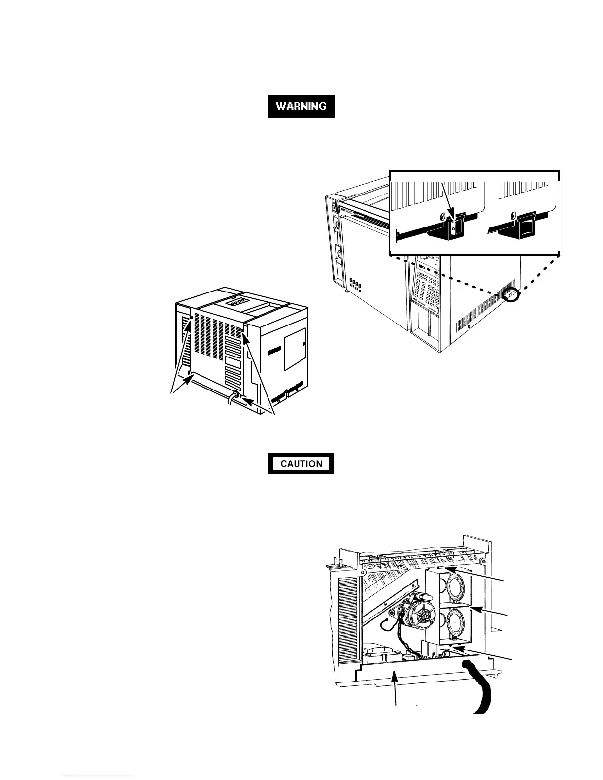
1. Set the main power line switch to the off position.
2. Disconnect the power cable from its receptacle.
3. Turn off all gas supplies.
4. Remove the four screws securing the rear
cover to the instrument.
5. Slide the rear cover towards the rear of the
instrument.
This procedure requires precautions against ESD (Electro-Static Discharge). Use a
groundedwrist strap (part no. 9300-0969 - large, or9300-0970 - small) connected
to a suitable ground. Failure to heed this caution may result in damage to the
instrument.
6. Use a 7-mm nut driver to remove the screw
securing the upper portion of the dual duct as-
sembly to the outer oven shell.
7. Use a Pozidriv screwdriver to loosen (but not
remove, the screw securing the lower portion of
the dual duct assembly to the outer oven shell.
8. Tilt the upper portion of the dual duct assembly
out of the rear of the instrument while lifting it
off of the loosened lower screw.
UPPER
SCREW
DUAL DUCT
ASSEMBLY
LOWER
SCREW
POWER SUPPLY
TRANSFORMER,
AND BASE
OFF ON
RED O VISIBLE
SCREWS
SCREWS
Artisan Scientific - Quality Instrumentation ... Guaranteed | (888) 88-SOURCE | www.artisan-scientific.com

 Loading...


