SVC 11-10
When disconnecting aplug, pull on the plug not on its wires. Pulling on the wires may
cause breakage.
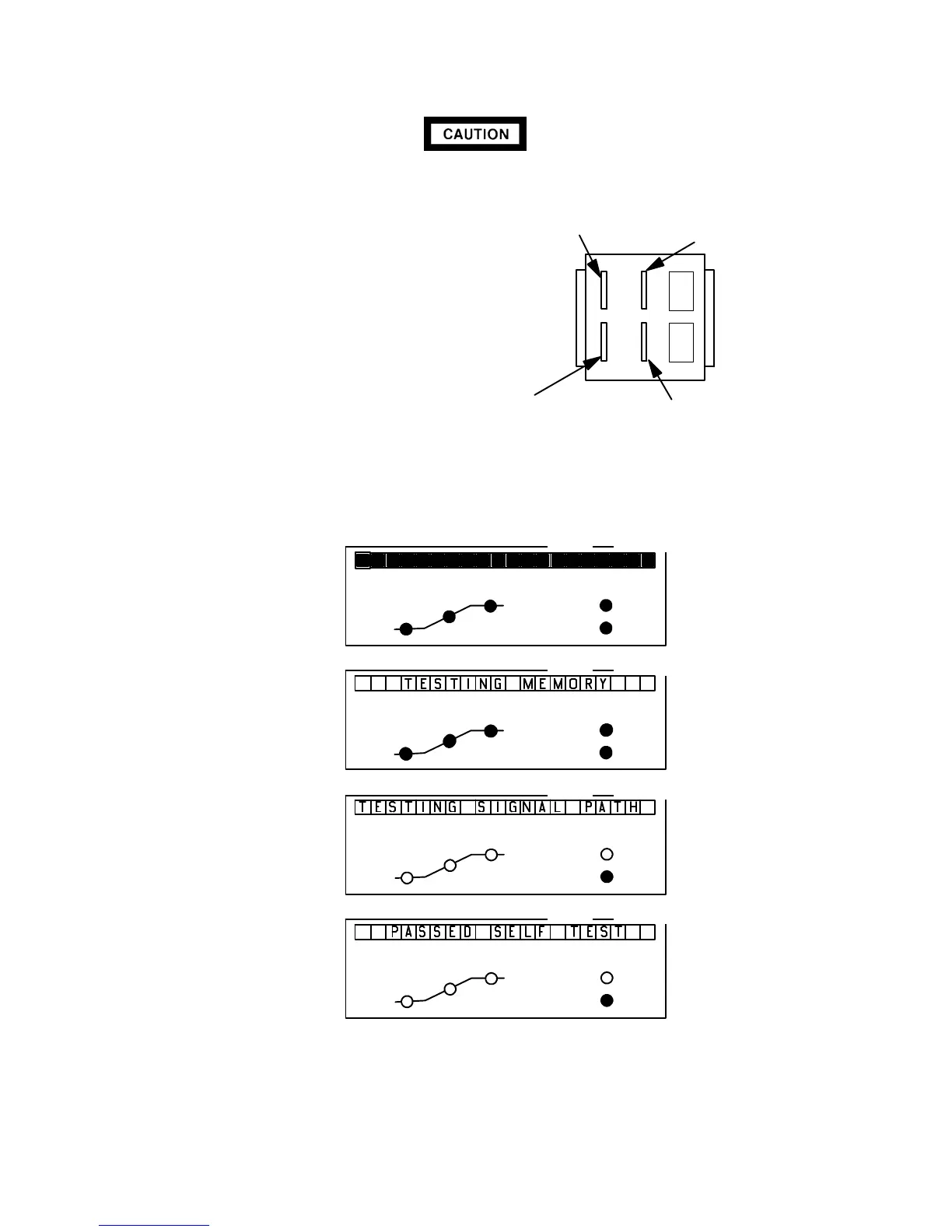
7. Remove the four push-on-type connectors
from the rear of the switch.
8. Connect wiring to power switch as shown in
illustration.
9. Install the power switch in its mounting slot (be-
low the main PCB.
10. Install the right side
panel and secure using
two screws.
11. Install the electronics
carrier top cover.
12. Restore all gas sup-
plies.
13. Restore power to the
instrument.
14. Observe the alphanu-
meric display as the in-
strument performs an
internal self-diagnostic
integrity check. to en-
sure that the instrument
shows expected normal
displays.
1A 1 1B
22A 2B
GREY
BLACK
BLACK/YELLOW
WHITE
OVEN
STATUS
RUN
NOT
READY
FINAL
TIME
RATE
INITIAL
TIME
OVEN
STATUS
RUN
NOT
READY
FINAL
TIME
RATE
INITIAL
TIME
OVEN
STATUS
RUN
NOT
READY
FINAL
TIME
RATE
INITIAL
TIME
OVEN
STATUS
RUN
NOT
READY
FINAL
TIME
RATE
INITIAL
TIME
ACTUAL SETPOINT
ACTUAL
ACTUAL
ACTUAL
SETPOINT
SETPOINT
SETPOINT
Test of display elements:
all alphanumeric and LED
elements are lit.
5890 Series II memory test
in progress.
5890A Self-testing in
progress.
LEDs off, except possibly
“NOT READY.”
Message indicating normal
termination of diagnostic
tests after power restoration.
User setpoints remain in
force.
LEDs off, except possibly
“NOT READY.”
NORMAL“INTEGRITY CHECK”
AT POWER-ON
Artisan Scientific - Quality Instrumentation ... Guaranteed | (888) 88-SOURCE | www.artisan-scientific.com

 Loading...


