SVC 2-19
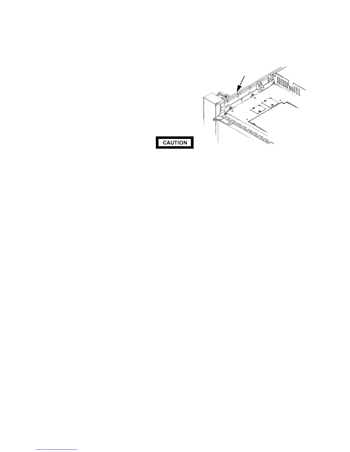
21. Bend the tubes running from the installed inlet
to the inlet flow control components so that
they lay within the “U”-shaped channels to the
left of the inlets.
22. Installthe tubes removed from the employed
flow controller in steps 9 and 10.
23. If employed, install the cryo-blast weldment
onto the inlet weldment.
24. Secure the inlet to the instrument using two
screws.
Handle the heater and sensor cartridges with care to prevent breakage. The cartridges
(particularly the smaller sensor cartridge) are fragile.
25. Carefully slide the heater and sensor cartridges into the heated block portion of the inlet.
26. Installthe air deflector and secure it to the weldment using one screw.
27. Installthe injection assembly, septum,PCOC insert spring, and insert (the injection assembly
secures the other items to the inlet weldment).
28. Installthe liner and all other hardware (except the column) removed in step 5.
29. Restore the supply gas pressure.
30. Check for leaks at all of the newly mated fittings.
31. Turn off the supply gas.
32. Remove the cap/plug from the end of the inlet.
33. Installthe column and associated hardware removed in step 5.
34. Installthe left side panel and secure using two screws.
35. Installthe injection port cover.
36. Restore power to the HP 5890 Series II.
SLOTS
Artisan Scientific - Quality Instrumentation ... Guaranteed | (888) 88-SOURCE | www.artisan-scientific.com

 Loading...


