ures are for illustration only, and more connection methods are
available.
• Any or all of the four SFP+ ports on the 6125G/XG can be used either for IRF or data connections.
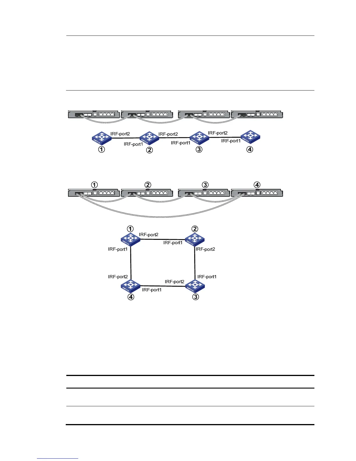
Figure 13 IRF fabric in daisy chain topology
Figure 14 IRF fabric in ring topology
Identifying physical IRF ports on the member switches
Identify the physical IRF ports on the member switches according to your topology and connection
scheme.
Table 3 sho
ws the physical ports that can be used for IRF connection.
Table 3 Physical IRF port requirements
Switch chassis Candidate physical IRF ports
HP 6125G
• 2 fixed IRF/SFP ports
• 1 internal 10-GE cross connect port
HP 6125G/XG
• 4 fixed SFP+ ports
• 1 internal 10-GE cross connect port

 Loading...


