Mak
e
a
list
of
these
assem
blies.
Delete
the
follo
wing assem
blies from
your
list as
they ha
ve
already b
een
v
eried
earlier
in
this section.
A10
digital
IF
A11
phase lo
ck
A12 reference
A13
fractional-N
analog
A14
fractional-N
digital
A18 displa
y
A19
graphics
pro
cessor
4.
Switc
h
o the
analyzer.
5.
Of
those
assem
blies
that
are
left
on
the
list,
remo
v
e
or
disconnect
them
from
the
analyzer
one
at
a
time.
T
able
5-4
sho
ws
the
best
order in
which
to
remo
v
e
them,
sorting
them
from
most
to least
accessible. T
able 5-4
also lists
an
y
asso
ciated
assem
blies
that
are
supplied
b
y
the
assem
bly
that
is
b
eing
remo
v
ed.
After
eac
h
assem
bly
is
remo
v
ed
or
disconnected
switc
h
on
the
analyzer
and
observ
e
the
LEDs.
Note
A
lways switch
o the
analyzer b
efor
e
r
emoving
or
disc
onne
cting
assemblies.
When extensiv
e disassem
bly
is
required,
refer
to
Chapter
14,
\Assem
bly
Replacemen
t
and
P
ost-Repair
Pro
cedures."
Refer
to
Chapter
13,
\Replaceable
P
arts,"
to
iden
tify
sp
ecic
cables
and
assem
blies
that
are
not
sho
wn
in
this
c
hapter.
If
all
the
LEDs
ligh
t,
the assem
bly
(or
one
receiving
p
o
w
er
from
it)
that
allo
ws
them
to
ligh
t
is
fault
y
.
If
the
LEDs
are
still
not
on
steadily
,
con
tin
ue
to
\Insp
ect
the
Motherb
oard."
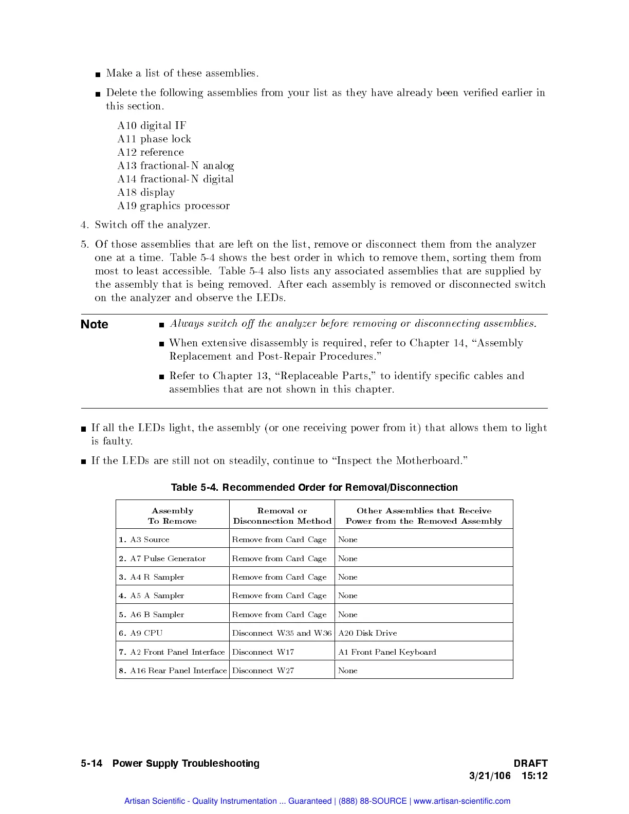
T
able
5-4.
Recommended
Order
for
Remo
v
al/Disconnection
Assem
bly
T
o
Remo
v
e
Remo
val
or
Disconnection
Metho
d
Other
Assemblies
that
Receiv
e
P
o
w
er
from
the
Remov
ed Assem
bly
1.
A3
Source
Remo
v
e
from
Card
Cage
None
2.
A7 Pulse Generator Remove from Card Cage
None
3.
A4 R Sampler Remove from Card
Cage
None
4.
A5 A Sampler Remove from Card Cage
None
5.
A6 B Sampler Remove from Card Cage None
6.
A9 CPU Disconnect W35 and W36 A20 Disk Drive
7.
A2 F
ront P
anel In
terface
Disconnect W17 A1 F
ront P
anel Keyb oard
8.
A16 Rear Panel Interface Disconnect W27 None
5-14 Power Supply Troubleshooting DRAFT
3/21/106 15:12
Artisan Scientific - Quality Instrumentation ... Guaranteed | (888) 88-SOURCE | www.artisan-scientific.com
 Loading...


