d.
Lo
osen
the
captiv
e
screw
on
the
b
ottom co
ver's
back
edge.
e.
Slide the
cov
er to
ward
the rear
of the
instrument.
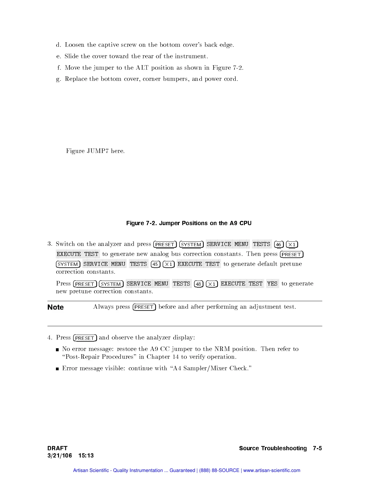
f. Mo
ve
the jump
er
to
the
AL
T
p
osition
as
sho
wn
in
Figure 7-2
.
g.
Replace
the
b
ottom co
ver,
corner bump
ers, and
po
wer
cord.
Figure JUMP7
here.
Figure
7-2.
Jumper P
ositions
on
the
A9
CPU
3.
Switc
h
on
the
analyzer
and
press
4
PRESET
5
4
SYSTEM
5
NN
N
N
N
N
N
N
N
N
N
N
N
N
N
N
N
N
N
N
N
N
N
N
N
NN
N
N
N
N
N
N
N
N
N
N
N
SERVICE
MENU
NN
N
N
N
N
N
N
N
N
N
N
N
N
N
N
N
TESTS
4
46
5
4
2
1
5
N
N
N
N
N
N
N
N
N
N
N
N
N
N
N
N
N
N
N
N
NN
N
N
N
N
N
N
N
N
N
N
N
N
N
N
N
N
EXECUTE
TEST
to
generate
new
analog
bus
correction
constants.
Then
press
4
PRESET
5
4
SYSTEM
5
N
N
N
N
N
N
N
N
N
N
N
N
N
N
NN
NN
N
N
N
N
N
N
N
N
N
N
N
N
N
N
N
N
N
N
N
N
SERVICE
MENU
N
N
N
N
N
N
N
N
N
N
N
N
N
N
NN
N
TESTS
4
45
5
4
2
1
5
N
N
N
N
N
N
N
N
N
N
N
N
N
N
NN
NN
N
N
N
N
N
N
N
N
N
N
N
N
N
N
N
N
N
N
N
N
EXECUTE
TEST
to generate
default pretune
correction
constan
ts.
Press
4
PRESET
5
4
SYSTEM
5
NN
NN
NN
NN
N
N
N
N
N
N
N
N
N
N
N
N
N
N
N
N
N
NN
NN
NN
NN
N
N
N
N
N
SERVICE
MENU
NN
NN
NN
NN
N
N
N
N
N
N
N
N
N
TESTS
4
48
5
4
2
1
5
NN
NN
NN
NN
N
N
N
N
N
N
N
N
N
N
N
N
N
N
N
N
N
NN
NN
NN
NN
N
N
N
N
N
EXECUTE
TEST
NN
NN
NN
NN
N
N
N
YES
to
generate
new
pretune
correction
constan
ts.
Note
Alw
ays
press
4
PRESET
5
before
and
after
p
erforming
an
adjustmen
t
test.
4. Press
4
PRESET
5
and observ
e the analyzer displa
y:
No error message: restore the A9 CC jump
er to the NRM position. Then refer to
\Post-Repair Pro cedures" in Chapter 14 to v
erify operation.
Error message visible: con
tinue with \A4 Sampler/Mixer Chec
k."
DRAFT
3/21/106 15:13
Source Troubleshooting 7-5
Artisan Scientific - Quality Instrumentation ... Guaranteed | (888) 88-SOURCE | www.artisan-scientific.com
 Loading...


