23
• When the IRF virtual device operates normally, only the MAD IP address of the master is effective
and the BFD session is down.
• When the IRF virtual device partitions, the MAD IP addresses of the masters in different IRF virtual
devices become effective to activate the BFD sessions to detect for multi-active IRF virtual device
collision.
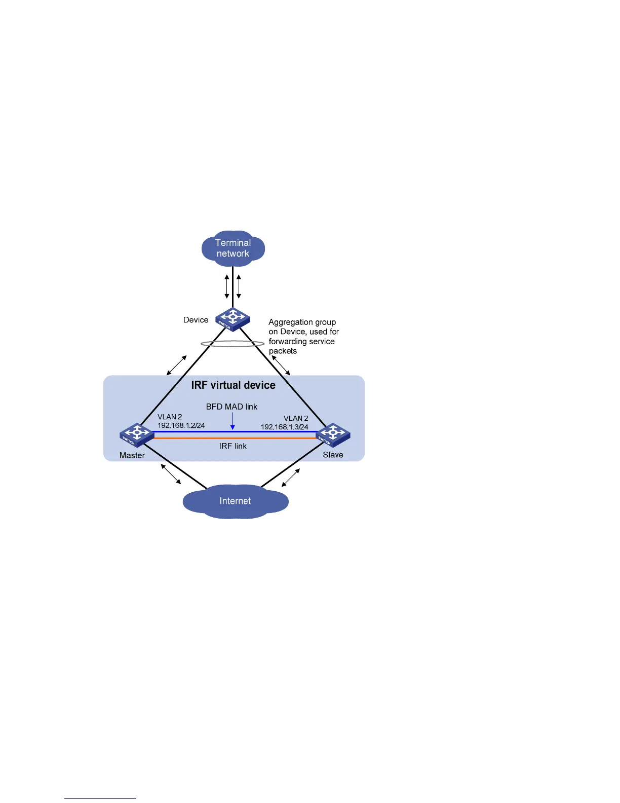
2. Network requirements
BFD MAD detection can be achieved with or without intermediate devices. In a BFD MAD network
without an intermediate device, connect all IRF member switches with dedicated BFD MAD links in the
full mesh topology, as shown in Figure 9. T
he interfaces connected by BFD MAD links must belong to the
same VLAN. In VLAN interface view, assign different IP addresses on the same network segment for
different member switches.
Figure 9 Network diagram for BFD MAD detection
3. Configuring BFD MAD detection
Configure BFD MAD detection by following these steps:
• Create a VLAN dedicated for BFD MAD detection (also required on the intermediate device if any)
• Select the physical IRF ports to be used for BFD MAD detection (at least one on each member
switch) and add them into the detection-dedicated VLAN (also required on the intermediate device
if any)
• Create VLAN interfaces for the detection-dedicated VLAN, enable BFD MAD detection on these
interfaces, and then assign MAD IP addresses for them.

 Loading...