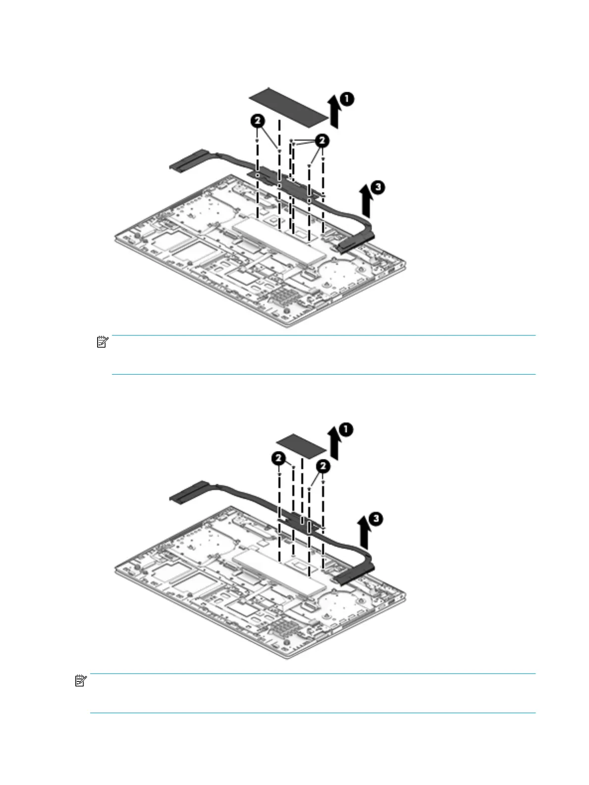
3. Remove the heat sink (3).
NOTE: Steps 4 and 5 apply only to computer models equipped with a graphics subsystem with UMA
memory. See steps 2 and 3 for heat sink removal information for computer models equipped with a
graphics subsystem with discrete memory.
4. Remove the four Phillips M2.0×3.2 screws (2) that secure the heat sink to the system board.
5. Remove the heat sink (3).
NOTE: The thermal material must be thoroughly cleaned from the surfaces of the heat sink
and the system board components each time the heat sink is removed. Replacement thermal material is
included with the heat sink and system board spare part kits.
58 Chapter 5 Removal and replacement procedures
 Loading...