Repair Tips
25
Go to cover page
HP L2025
7
HP L2025
HP L2025
27
0. Warning
All ICsand many other semi-conductors are susceptible to
electrostaticdischarges (ESD). Careless handling during
repair can reduce life drastically. When repairing, makesure
that you are connectedwith thesamepotential as the mass
of the un
itvia a wristwrap with resistance.Keep components
and toolsalso atthesamepotential!
1. Servicing of SMDs (Surface MountedDevices)
1.1 Generalcautions on handling and storage
-Oxidation on the terminals of SMDs resultsin poorsoldering.
Do not handle SMDs with bare hands.
-Avoidusing storageplaces that are sensitive to oxidation
such as places with sulphur or chlorine gas,direct sunl
ight,
high temperatures orahigh degree of humidity. The
capacitance or resistance value of the SMDs maybe
affectedbythis.
- Rough handling of circuitboards containing SMDs may
cause damage to the componentsas
well as the circuit
boards.Circuitboards containing SMDsshould never be
bent or flexed. Different circuitboardmaterialsexpand and
contract atdifferent rates whenheatedor cooled and the
componentsand/orsolder conn
ections maybe damaged
due to thestress.Never rub orscrape chip componentsas
this maycause the value of the component to change.
Similarly, do not slide the circuitboard across any surface.
1.2 RemovalofSMDs
-Heatthesolder (for 2-3 seconds) at each terminalofthe
chip.Bymeans of litz wire and aslight horizontalforce,
small components canberemovedwith thesoldering iron.
Theycan alsoberemovedwith asolder sucker (see Fig.
1A)
While holding the SMD with a pair of tweezers,takeitoffgently using the
soldering iron's heat appliedtoeach terminal(see Fig. 1 B).
- Remove theexcess solder on thesolder lands by means of
litz wire orasolder sucker (see Fig. 1C).
1.3 Caution on removal
-Whenhandling thesoldering.iron. use suitable pressure and be careful.
-When removing the chip, do not use undue force with the pair of tweezers.
- Thesoldering iron to be used(approx. 30 W) should
preferably beequippedwith a thermal control (soldering
temperature: 225 to 250 C).
- The chip, onceremoved, mustnever bereused.
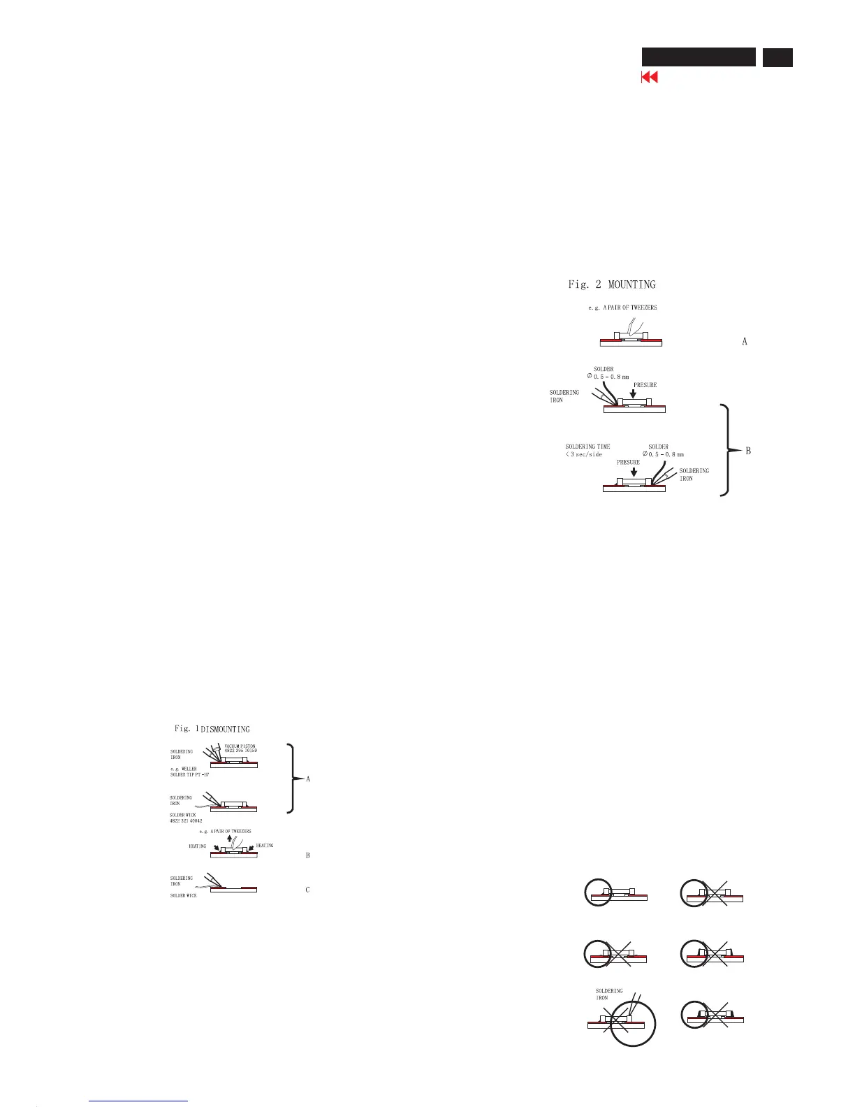
1.4 Attachment of SMDs
- Locate the SMD on thesolder lands by means of tweezers
and solder the component on oneside.Ensure thatthe
component is positionedcorrectly on thesolder lands (see Fig.2A).
-Next complete thesoldering of the terminals of the
component (
see Fiq. 2B).
2. Caution when attaching SMDs
-When soldering the SMD terminals, do not touch them
directly with thesoldering iron. Thesoldering should be
doneasquickly as possible,care mustbe takentoavoid
damage to the terminals of the SMDs themselves.
-Keep the SMD's body in conta
ct with the printedboardwhen
soldering.
- Thesoldering iron to be used(approx. 30 W ) should
preferably beequippedwith a thermal control (soldering
temperature: 225 to 250 C).
- Soldering should not be done outside thesolder land.
- Soldering flux (of rosin) maybe used, but should not be
acidi
c.
- After soldering, letthe SMD cool down gradually at room
temperature.
- The quantity of solder mustbeproportionaltothesize of the
solder land. If the quantity is too great, the SMD might
crack or thesolder lands might be torn loose from the
print
edboard(see Fig. 3).
Fig.3 Examples
Right
HP L1940

 Loading...