DDC Instructions
Pin No. Description
1 T.M.D.S. data2-
2 T.M.D.S. data2+
3 T.M.D.S. data2 shield
4 No Connect
5 No Connect
6 DDC clock
7 DDC data
8 No Connect
9 T.M.D.S. data1-
10 T.M.D.S. data1+
11 T.M.D.S. data1 shield
12 No Connect
13 No Connect
14 +5V Power
15 Ground (for +5V) - Cable detect
16 Hot plug detect
17 T.M.D.S. data0-
18 T.M.D.S. data0+
19 T.M.D.S. data0 shield
20 No Connect
21 No Connect
22 T.M.D.S clock shield
23 T.M.D.S. clock+
24 T.M.D.S. clock-
General
DDC Data Re-programming
In case the DDC data memory IC or main EEPROM which storage all
factory settings were replaced due to a defect, the serial numbers have
to be re-programmed "Analog DDC IC, Digital DDC IC & EEPROM".
It is advised to re-soldered DDC IC and main EEPROM from the old
board onto the new board if circuit board have been replaced, in this case
the DDC data does not need to be re-programmed.
Additional information
Additional information about DDC (Display Data Channel) may be
obtained from Video Electronics Standards Association (VESA).
Extended Display Identification Data(EDID) information may be also
obtained from VESA.
1. An i486 (or above) personal computer or compatible.
2. Microsoft operation system Windows 95/98 .
Y o Install the EDID_PORT_Tool under Win2000/XP . As
Fig. 1 .
A. Cody the "UserPort.sys" to C:\WINNT\system32\drivers(win2000)
C:\WINDOWS\system32\drivers(winXP)
B. Running " io.exe" everytime, Before you start to programming
edid data .
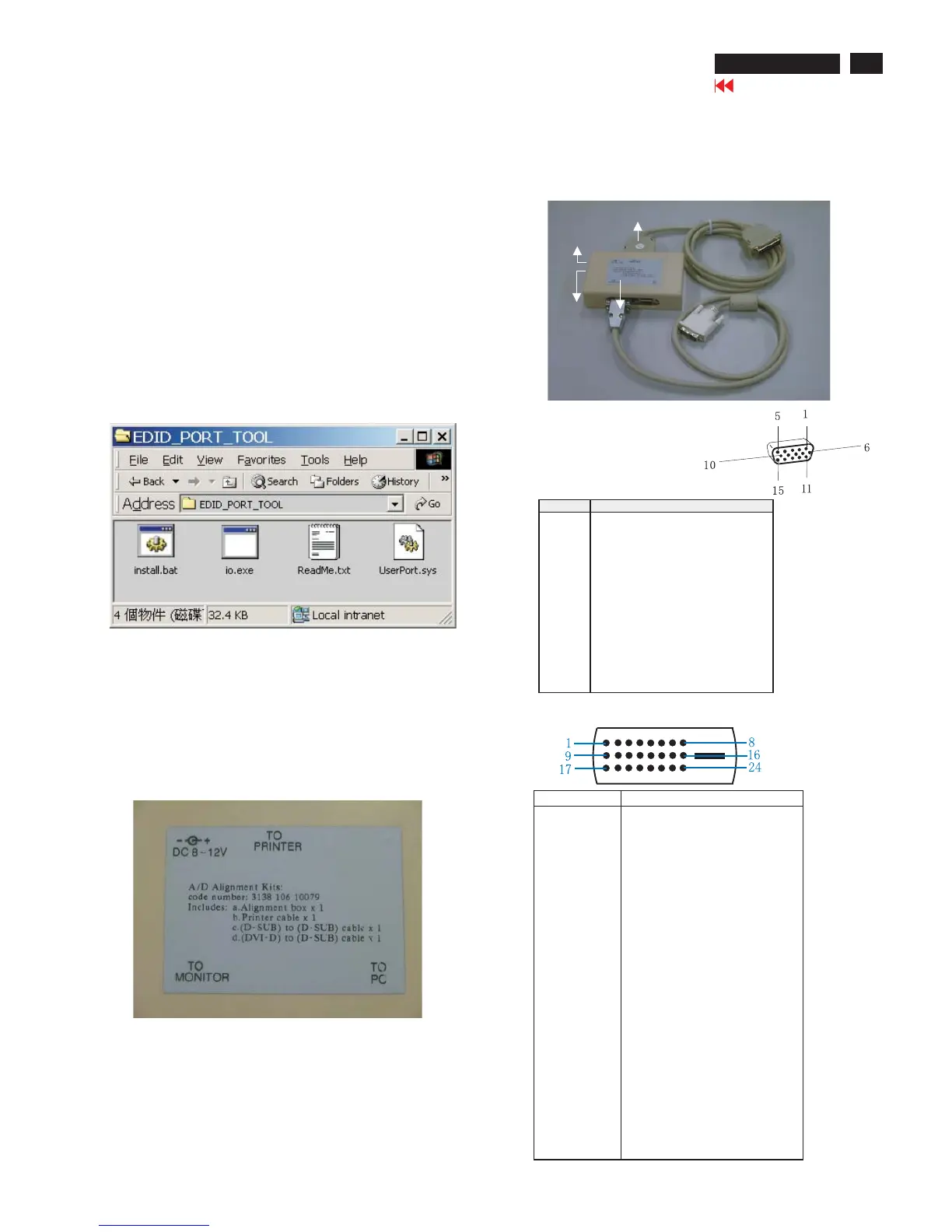
4. A/D Alignment kits (12NC: 3138 106 10079):
inclusion : a. Alignment box x1 (Fig. 2)
b. Printer cable x1
c. (D-Sub) to (D-Sub) cable x1
D. (D-Sub) to (DVI) cable x1
System and equipment requirements
ou have t
3. EDID46.EXE program
Fig. 1
Fig. 1
Fig. 2
To Monitor
D-sub/DVI cable
DC 8~12V
To Printer port
Power
indicator
Note: The alignment box has already build-in a batteries socket for
using batteries (8~12V) as power source. Pull out the socket by
remove four screws at the rear of box. Please do not forget that
remove batteries after programming. The energy of batteries can
only drive circuits for a short period of time.
PIN No. SIGNAL
1 Red video input
2 Green video input / sync on green
3 Blue video input
4GND
5 GND - Cable detect
6RedvideoGND
7 Green video GND
8 Blue video GND
9DDC+3.3Vor+5V
10 Logic GND
11 GND
12 Serial data line (SDA)
13 H-sync / H+V
14 V-sync
15 Data clock line (SCL)
Pin assignment
A. 15-pin D-Sub Connector
B. Input DVI -D Connector pin
Fig. 3
Go to cover page
15
HP L1940
 Loading...