TELEVISION/MONITOR SAFFTY GUIDELINES FOR THE PROFESSIONAL SERVICE TECHNICIAN
Safety Checks
Fire and Shock Hazard
Implosion
X-radiation
After the original service problem has been corrected,a complete safety check
shouldbemade.Besuretocheckovertheentireset,notjusttheareas
where you have worked. Some previous servicer may have left an unsafe
condition,which could be unknowingly passed on to your customer. Be sure
tocheckallofthefollowing:
1. Be sure all components are positioned in such a way as to avoid the
possibility of adjacent component shorts. This is especially important
on those chassis which are transported to and from the service shop.
2. Never release a repaired unit unless all protective devices such as
insulators, barries, covers, strain reliefs, and other hardware have been
installed in accordance with the original design.
3. Solderingandwiringmustbeinspectedtolocatepossiblecoldsolder
joints,solder splashes,sharp solder points, frayed leads, pinched leads,
or damaged insulation ( including the ac cord).Be certain to remove
loose solder balls and all other loose foreign particles.
4. Check across-the-line components and other components for physical
evidence of damage or deterioration and replace if necessary. Follow
original layout,lead length, and dress.
5. No lead or component should touch a receiving tube or a resistor rated
at1wattormore.Leadtensionaroundprotrudingmetalsurfacesor
edges must be avoided.
6. Critical components having special safety characteristics are identified
withansbytheRef.No.inthepartslistandenclosedwithinabrokenline
* (where several critical components are grouped in one area) along with
the safety symbols on the schematic diagrams and/or exploded views.
7. When servicing any unit, always use a separate isolation transformer
forthechassisFailuretouseaseparateisolationtransformermay
expose you to possible shock hazard, and may cause damage to
servicing instruments.
8. Many electronic products use a polarized ac line cord (one wide pin on
theplug.)Defeatingthissafetyfeaturemaycreateapotentialhazardto
theserviceandtheuser.Extensioncordswhichdonotincorporatethe
polarizing feature should never be used.
9. After reassembly of the unit, always perform an leakage test or resistance
testfromthelinecordtoallexposedmetalpartsofthecabinet.Alsocheck
all metal control shafts(with knobs removed), antenna terminals, handles,
screws,etc.tobesuretheunitmaybesafetyoperatedwithoutdangerof
electrical shock.
*Brokenline
1. All picture tubes used in current model receivers are equipped with an
integral implosion system. Care should always be used, and safety
glasses worn,whenever handling any picture tube. Avoid scratching or
otherwise damaging the picture tube during installation.
2. Use only replacement tubes specified by the manufacturer.
1. Be sure procedures and instructions to all your service personnel cover
the subject of X-radiation. Potential sources of X-rays in TV receivers are
the picture tube and the high voltage circuits. The basic precaution which
must be exercised is to keep the high voltage at the factory recommended
level.
2. ToavoidpossibleexposuretoX-radiationandelectricalshock,onlythe
manufacturer's specified anode connectors must be used.
3. It is essential that the service technician has an accurate HV meter
availableatalltimes.Thecalibrationofthismetershouldbechecked
periodically against a reference standard.
4. When the HV circuitry is operating properly there is no possibility of an x-
radiation problem. High voltage should always be kept at the
manufacturer's
ratedvalue-nohigher-foroptimumperformance.Everytimeacolorsetis
serviced, the brightness should be run up and down while monitoring the
HV with a meter to be certain that the HV is regulated correctly and does
not exceed the specified value. We suggest that you and your technicians
review test procedures so that HV and HV regulation are always checked as
a standard servicing procedure, and the reason for this prudent routine is
clearly understood by everyone. It is important to use an accurate and
reliable HV meter. It is recommended that the HV recorded on each
customer'sinvoice,whichwilldemonstrateaproperconcernforthe
customer's safety.
5. When troubleshooting and making test measurements in a receiver with
a problem of excessive high voltage, reduce the line voltage by means of
aVariactobringtheHVintoacceptablelimitswhiletroubleshooting.Do
:
:
WARNING OFF
SERVICE NOTE
Before removing the CRT anode cap, turn the unit and short the HIGH VOLTAGE to the CRT DAG ground.
The CRT DAG is not at chassis ground.
6. New picture tubes are specifically designed to withstand higher operathng
voltages without creating undesirable X-radiation. It is strongly
recommended that any shop test fixture which is to be used with the new
higher voltage chassis be equipped with one of the new type tubes
designed for this service. Addition of a permanently connected HV meter
totheshoptestfixtureisadvisable.TheCRTtypesusedin thesenew
sets should never be replaced with any other types, as this may result in
excessive X-radiation.
7. It is essential to use the specified picture tube to avoid a possible X-diation
problem.
8. MostTVreceiverscontainsometypeofemergency"HoldDown"circuitto
prevent HV from rising to excessive levels in the presence of a failure
mode. These various circuits should be understood by all technicians
servicing them, especially since many hold down circuits are inoperative
as long as the receiver performs normally.
1. Unplugtheaclinecordandconnectajumperbetweenthetwoprongsof
the plug.
2. Turn on the power switch.
3. Measuretheresistancevaluebetweenthejumperedacplugandall
exposed cabinet parts of the receiver, such as screw heads, antennas,
andcontrolshafts.Whentheexposedmetallicparthasareturnpathto
the chassis, the reading should be between 1 megohm and 5.2 megohms.
Whentheexposedmetaldoesnothaveareturnpathto thechassis,the
reading must be infinity. Remove the jumper from the ac line cord.
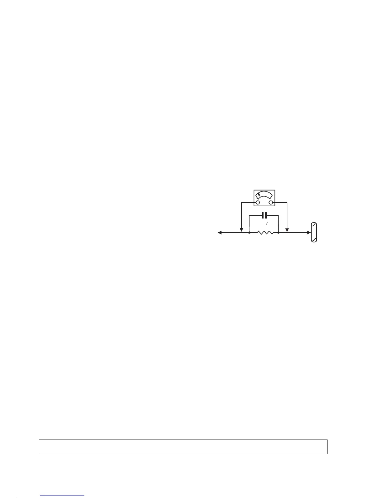
1. Donotuseanisolationtransformerforthistest.Plugthecompletely
reassembled receiver directly into the ac outlet.
2. Connect a 1.5k, 10w resistor paralleled by a 0.15uf. capacitor between
each exposed metallic cabinet part and a good earth ground such as a
water pipe, as shown above.
3. Useanacvoltmeterwithatleast5000ohmsvoltsensitivitytomeasure
the potential across the resistor.
4. Thepotentialatanypointshouldnotexceed0.75volts.Aleakagecurrent
tester may be used to make this test; leakage current must not exceed
0.5milliamps.Ifameasurementisoutsideofthespecifiedlimits,thereis
apossibilityofshockhazard. Thereceivershouldberepairedand
rechecked before returning it to the customer.
5. Repeat the above procedure with the ac plug reversed.( Note: An ac
adapter is necessary when a polarized plug is used. Do not defeat the
polarizing feature of the plug.)
The primary source of X-radiation in this television receiver is the picture
tube. The picture tube utilized in this chassis is specially constructed to limit
X-radiation emissions. For continued X-radiation protection, the replacement
tube must be the same type as the original, including suffix letter, or a Philips
approved type.
Many electrical and mechanical parts in Philips television sets have special
safety related characteristics. These characteristics are often not evident from
visual inspection nor can the protection afforded by them necessarily be
obtained by using replacement components rated for higher voltage, wattage,
etc. The use of a substitute part which does not have the same safety
characteristics as the Philips recommended replacement part shown in this
service manual may create shock, fire, or other hazards
Leakage Current Cold Check
Leakage Current Hot Check
Picture Tube Replacement
Parts Replacement
1500 ohm, 10W
0.15 uF
WATER
PIPE
EARTH
GROUND
TO
INSTRUMENTS
EXPOSED
METAL PARTS

 Loading...