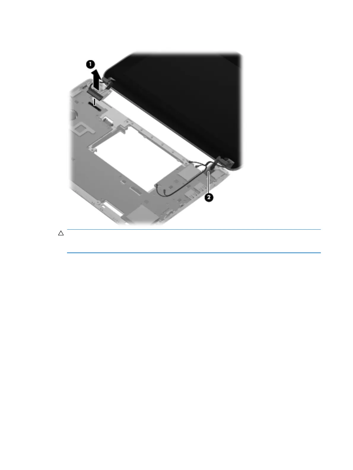
7. Release the wireless antenna cables (2) from the clip built into the base enclosure.
CAUTION: Support the display assembly when removing the following screws. Failure to
support the display assembly can result in damage to the display assembly and other device
components.
8. Remove the 2 Phillips 2.5×5.0 screws (1) that secure the display assembly to the base
enclosure.
58 Chapter 4 Removal and replacement procedures
Download from Www.Somanuals.com. All Manuals Search And Download.