2-21
Installing the Switch
Installation Procedures
Installing the Switch
Each pair can provide a maximum of 408 watts of PoE power to a switch if
only one port is used. If the second port of a pair is used, then both ports supply
204 watts each. Again, it is important to understand the PoE power
requirements of the switches. For further information regarding the 610 EPS
PoE capabilities, see the PoE Planning and Implementation Guide, which is
on the ProCurve Web site at www.hp.com/go/procurve/manuals, (See page 1-13).
600 RPS/EPS LEDs
For a complete description of the LEDs see the documentation that came with
the 600 RPS/EPS.
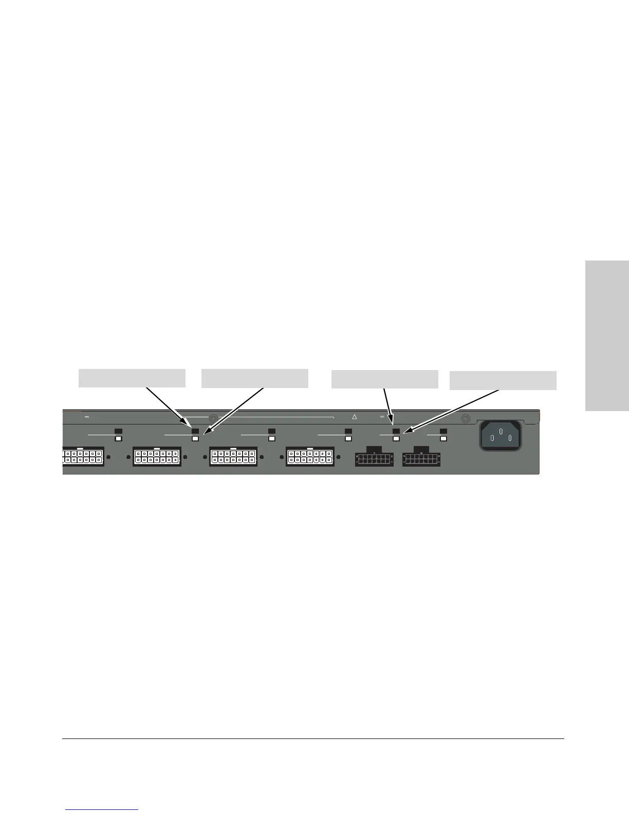
The 600 RPS/EPS LEDs are located on the back of the device. These LEDs are
duplicated on the front of the device for your convenience. The following
graphic shows an example of the back of the 600 EPS/RPS. There are two
green LEDs for each RPS and EPS port:
■ Device Connected
■ Power Status
Figure 2-12. RPS/EPS status LEDs
R3 R4 R5 R6 E1
Device
Connected
Pow er
Status
E2
RPS 3 RPS 4 RPS 5 RPS 6 EPS 1 EPS 2
EPS Power: 50V 370W total for PoE applications. Power is shared when both ports are used.
PS Power: 12V backup to one connected device. Lowest-numbered port has priority.
Line: 50/60 Hz.
10
0
-
2
40 V~ 9.1A (9,1A)
!
EPS Power Status LED
EPS Device Connected LED
RPS Power Status LED
RPS Device Connected LED
 Loading...