2-19
Installing the Series 5400zl Switches
Installation Procedures
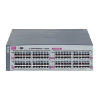
Installing the Series 5400zl
Switches
7. Connect the Switch to a Power Source
1. Plug the included power cord into the switch’s power connector and into
a nearby properly grounded AC power source.
If you have installed a redundant power supply module into the switch, it
should be connected to a separate AC power source. Then, if there is a
power outage from one of the AC sources, the switch will continue to
operate by power coming from the other source.
See the ProCurve Switch zl RPS Installation Guide for additional
information.
2. Re-check the LEDs during self test. See “LED Behavior” on page 2-13.
8. Connect the Network Devices
The type of network connections you will need to use depends on the types
of switch modules you have installed in your Series 5400zl Switch. See the
documentation accompanying the modules for cabling configurations and
procedures for those modules.
In general for all the modules, when a network cable from an active network
device is connected to the switch, the Link LED for the switch port should go
on. If the Link LED does not go on, use the table below to help solve the
problem, and see the module documentation for troubleshooting procedures.
Condition Diagnostic Tip
Port LED is
still off when
a cable is
connected
Try the following procedures:
• For the indicated port, verify both ends of the cabling, at the switch and the connected device, are
securely connected.
• Verify the connected device and switch are both powered on and operating correctly.
• Verify you have used the correct cable type for the connection:
– for all twisted-pair connections, the RJ-45 connectors on the Series 5400zl Switches allow you
to use either straight-through cable or crossover cable when the port is in the “Auto”
configuration.
– for fiber-optic connections, verify the transmit port on the switch is connected to
the receive port on the connected device, and the switch receive port is connected to
the transmit port on the connected device.
See appendix B, “Switch Ports and Network Cables” for information on cables.
• Verify the port has not been disabled through a switch configuration change.
• Verify the connection parameters in the configurations of the switch port and the connected
device match. Mismatched configurations are a frequent cause of connection problems.
You can use the console interface, or, if you have configured an IP address on the switch, use the
web browser interface, or ProCurve Manager network management software to determine the
state and configuration of the port and re-enable the port if necessary.
• If the other procedures don’t resolve the problem, try using a different port or a different cable.
 Loading...