Removal and replacement procedures 48
PCIe riser board
To remove the component:
1. Power down the server (on page 25).
2. Remove all power:
a. Disconnect each power cord from the power source.
b. Disconnect each power cord from the server.
3. Extend the server from the rack (on page 26).
4. Remove the access panel ("Access panel" on page 27).
5. Remove the PCI riser cage ("PCI riser cage" on page 46).
6. Remove any installed expansion boards ("Flash-backed write cache procedures" on page 40,
"Expansion boards" on page 47).
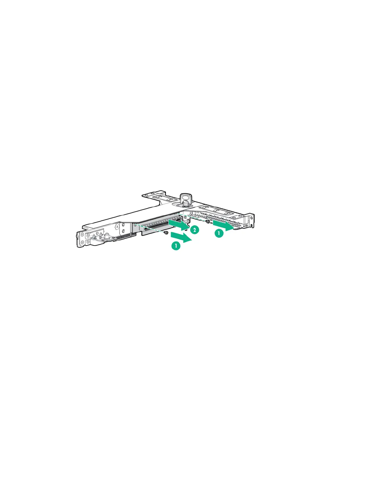
7. Remove the PCIe riser board.
The x16 PCIe riser board (shown) has 2 screws to remove from the assembly; the x8 PCIe riser
board (on the other side of the PCI riser cage) has 3 screws to remove from the assembly.
To replace the component, reverse the removal procedure.
DIMMs
To remove the component:
1. Power down the server (on page 25).
2. Remove all power:
a. Disconnect each power cord from the power source.
b. Disconnect each power cord from the server.
3. Extend the server from the rack (on page 26).
4. Remove the access panel ("Access panel" on page 27).
5. If installed, remove the FBWC capacitor pack ("FBWC capacitor pack" on page 41).
 Loading...