HP V-M200 802.11n Access Point Quickstart 2 Important information to read before installing
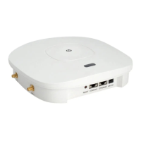
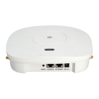
Reset button
Press and quickly release the Reset button to restart the V-M200. To reset the V-M200 to
factory defaults, press and hold the button until the status lights blink three times, then
release. If you keep the Reset button pressed for too long, the V-M200 will switch into
maintenance mode as indicated by a rapid blinking of the status lights. If this occurs, power
cycle the V-M200 and repeat the factory-default reset procedure.
Status lights
The status lights (left to right) indicate the following:
Important information to read before installing
Prior to installing or using the V-M200, make sure that the installation plans are in
compliance with RF and other regulations, such as building and wiring codes, safety,
channel, indoor/outdoor restrictions, and license requirements for the intended country
of use. It is the responsibility of the end user to ensure that installation and use comply
with local safety and radio regulations.
Surge protection and grounding: Make sure that proper surge protection and grounding
precautions are taken according to local electrical code. Failure to do so may result in
personal injury, fire, equipment damage, or a voided warranty. The HP Networking hardware
warranty provides no protection against damage caused by static discharge or a power
surge.
Cabling: You must use the appropriate cables, and where applicable, surge protection, for
your given region. For compliance with EN55022 Class-B emissions requirements use
shielded Ethernet cables. At least Cat 5e cabling is required.
Country of use: In some regions, you are prompted to select the country of use during setup.
Once the country has been set, the V-M200 will automatically limit the available wireless
channels, ensuring compliant operation in the selected country. Entering the incorrect
country may result in illegal operation and may cause harmful interference to other systems.
Safety: Take note of the following safety information during installation.
• If your network covers an area served by more than one power distribution system, be
sure all safety grounds are securely interconnected.
• Network cables may occasionally be subject to hazardous transient voltages (caused by
lightning or disturbances in the electrical power grid).
• Handle exposed metal components of the network with caution.
• The V-M200 is powered-on when the Ethernet port is plugged into a PoE power source
or when an external power supply is connected.
• The V-M200 and all interconnected equipment must be installed indoors within the
same building, including all PoE-powered network connections as described by
Environment A of the IEEE 802.3af standard.
Powering the V-M200
The V-M200 can be powered by:
• The provided external power adapter.
• A 10/100 or 10/100/1000 PoE-enabled switch. Various PoE-enabled switches are
available from HP Networking.
• An HP Networking 1-Port Power Injector (J9407A).
Caution: If the V-M200 will be powered by a user-supplied PoE power injector, use
only a gigabit-compatible power injector. PoE injectors designed for 10/100
networks only are NOT compatible with the V-M200.
Installation
The V-M200 can be mounted on a wall, or placed on a desktop or any other suitable horizontal
surface. The rubber feet prevent the V-M200 from sliding or scratching the surface.
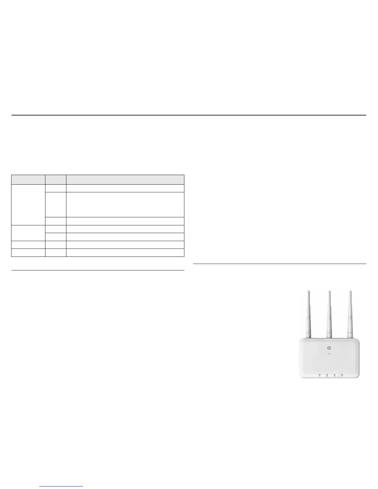
Mounting the V-M200 on a wall
You can mount the V-M200 on a wall with the
antennas at the top. Position all three antennas so
that they run straight up parallel to the wall and
perpendicular to the V-M200 body as illustrated to
the right.
Select mounting screws with a non-counter-sunk
screw head approximately 6 mm (.25 inches) in
diameter so that the screw head fits into the
mounting holes on the back of the V-M200. The
screws should have an approximate length of 25
mm to 30 mm (1 to 1.25 inches) and a diameter of
3.5 mm (.14 inches).
For drywall, it is recommended that wall anchors be
used with the screws. In North America, a #6 screw
with matching wall anchor works well.
Light State Description
Power
Off The V-M200 has no power.
Blinking The V-M200 is starting up. If the Power light continues to
blink after several minutes, it indicates that the software failed
to load. Reset or power cycle the V-M200. If this condition
persists, contact www.hp.com/networking/support.
On The V-M200 is fully operational.
Ethernet
Off The port is not connected or there is no activity.
Blinking The port is transmitting or receiving data.
WLAN 2.4GHz Blinking Radio is transmitting or receiving data in 802.11b/g/n mode.
WLAN 5GHz Blinking Radio is transmitting or receiving data in 802.11a/n mode.
 Loading...