Component locations
The following illustration and table identify computer system board components.
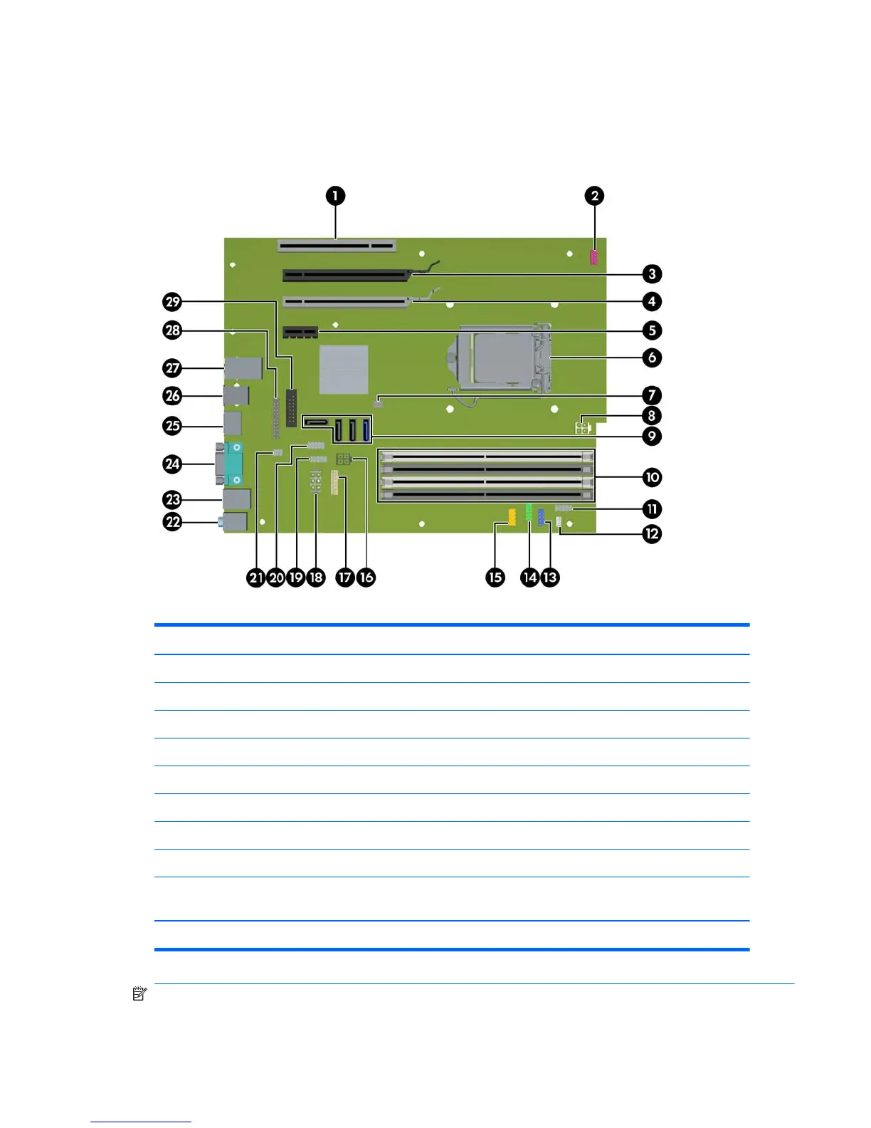
Figure 5-1 System board component locations
Table 5-2 System board components ID
Item Component Item Component Item Component
1 PCI 32/33 11 Front power button/LED 21 Solenoid hood lock
2 Front system fan 12 Speaker 22 Audio
3 PCIe2 x16(16) 13 Front audio 23 Keyboard/mouse
4 PCIe x16(4) 14 Front USB 24 VGA/1st serial
5 PCIe x1 15 Front USB 25 Display port
6CPU socket 16SATA power 26USB
7 Chassis intrusion switch 17 Power COMM 27 Network/USB
8 CPU power 18 Main power 28 Parallel
9 SATA ports (3) and eSATA
port (1)
19 Internal USB1 29 2nd serial
10 Memory sockets 20 Internal USB2/DASH
NOTE: All SATA ports are eSATA compatible, even though only one port is labeled for eSATA on
the system board.
ENWW
Removing and installing components
67