10
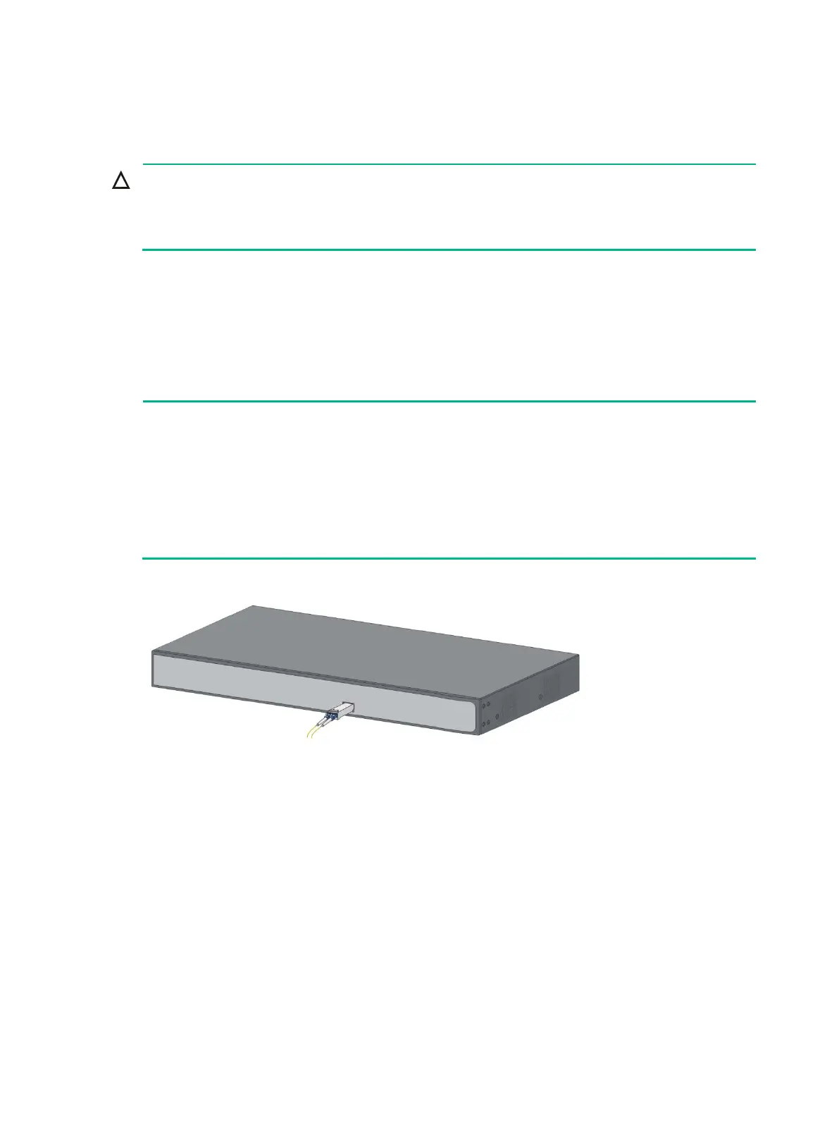
Installing the SFP/SFP+ transceiver module and optical
fibers
Hold the SFP/SFP+ transceiver module by its two sides when you install or remove the
module. Do not touch the golden plating of the module.
• Remove the optical fiber, if any, from a transceiver module before installing it.
To install an SFP/SFP+ transceiver module and optical fibers:
1. Wear an ESD wrist strap and make sure it makes good skin contact and is reliably grounded.
2. Pivot the clasp of the module up. Holding the module, gently push the module into the slot
until it has firm contact with the slot (when the top and bottom spring tabs catch in the slot).
3. Remove protective sleeves from optical fibers, and the dust plug from the transceiver module.
4. Connect the LC connectors of the optical fibers to the transceiver module.
Keep the protective sleeves for future use.
The fiber ports on the HPE 1420-24G-2SFP Switch operate in autonegotiation mode. For the
link between the switch and the peer device to operate correctly, verify that the fiber ports on
the peer device also operate in autonegotiation mode.
For the link between the HPE 1420-24G-2SFP+ 10G Uplink Switch and the peer device to
operate correctly, set the fiber ports on both devices to operate at the same speed in full
Figure 13 Installing the SFP/SFP+ transceiver module and optical fibers
Connecting the AC power cord
Only the HPE 1420-16G, 1420-24G, 1420-24G-2SFP, 1420-24G-2SFP+ 10G Uplink, and 1420-24G-
PoE+ (124W) support an AC power supply.
To connect the AC power cord:
1. Wear an ESD wrist strap and make sure it makes good skin contact and is reliably grounded.
2. Connect one end of the grounding cable to the grounding screw on the rear panel, and
connect the other end to the ground.
3. Make sure the correct power source is used.
4. Connect one end of the AC power cord to the AC power receptacle on the switch.
5. Connect the other end of the AC power cord to the AC power outlet.
6. Examine the power LED. If it is ON, the power connection is correct.

 Loading...