6
Horizontal surface mounting
Reserve a clearance of 10 cm (3.9 in) around the chassis for heat dissipation.
• Do not place heavy objects on the switch.
To mount the switch on a horizontal surface:
1. Verify that the horizontal surface is sturdy and reliably grounded.
2. Place the switch bottom up, and clean the round holes in the chassis bottom with a dry cloth.
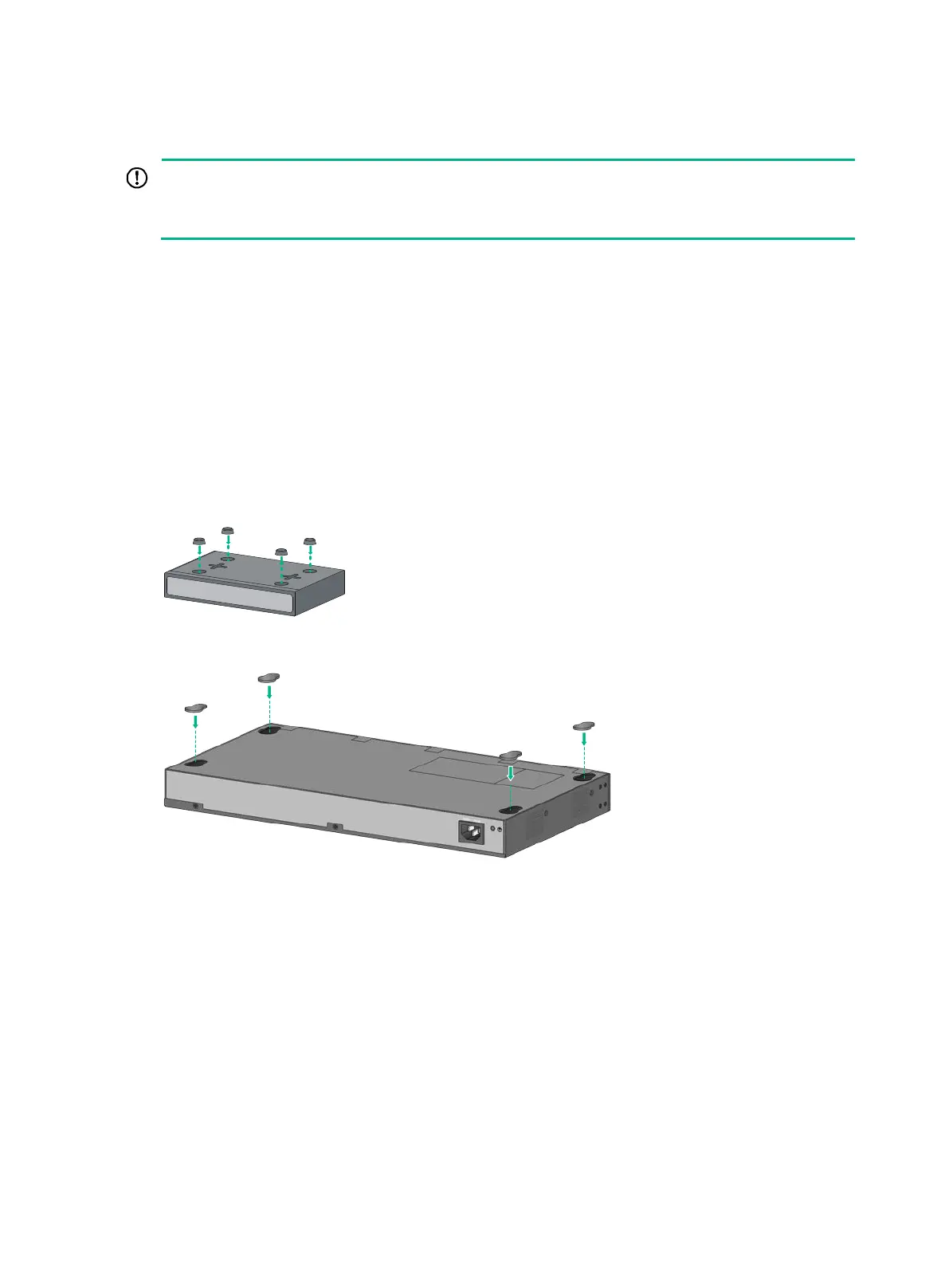
3. Select rubber feet for the switch.
The HPE 1420-5G, 1420-5G-PoE+ (32W), 1420-8G, 1420-8G-PoE+ (64W), and 1420-
16G switches use Type-A rubber feet, as shown in Figure 5.
The HPE 1420-24G, 1420-24G-2SFP, 1420-24G-2SFP+ 10G Uplink, and 1420-24G-
PoE+ (124W) switches use Type-B rubber feet, as shown in Figure 6.
4. Attach the rubber feet to the four round holes in the chassis bottom.
5. Place the switch upside up on the horizontal surface.
Figure 5 Attaching Type-A rubber feet
Figure 6 Attaching Type-B rubber feet
Wall mounting
Only the HPE 1420-5G, 1420-5G-PoE+ (32W), 1420-8G, 1420-8G-PoE+ (64W), and 1420-16G
switches can be installed on a wall. The type of screws used to mount the switch on the wall depends
on the wall type. This section uses a concrete wall as an example.
The screws must be a minimum of 3 mm (0.12 in) and a maximum of 3.8 mm (0.15 in) in diameter.
The screw head must be a minimum of 6 mm (0.24 in) and a maximum of 9.8 mm (0.59 in) in diameter.

 Loading...