16
LP-505 REV. 4.29.14
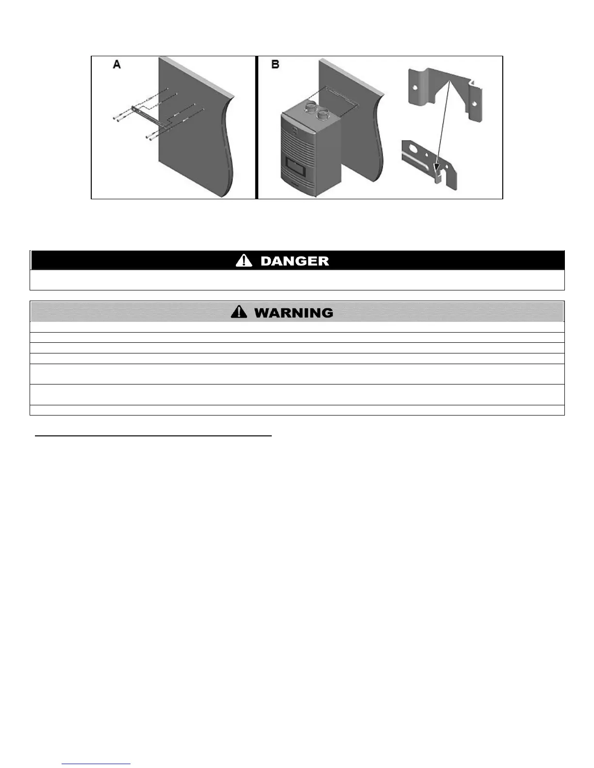
Figure 4 – Wall Mounting the Water Heater
PART 5 – VENTING
Vent this water heater in accordance with these instructions. Failure to do so will result in property damage, severe personal injury, or
death.
DO NOT mix vent systems or materials unless specifically told to do so in this manual.
DO NOT thermally insulate the exhaust vent or intake pipes.
DO NOT use an electric damper, vent damper, or draft hood with this water heater.
DO NOT locate the exhaust vent or intake pipe terminations where exposed to prevailing winds.
Moisture will be produced by the exhaust vent. Take precautions when determining exhaust vent termination. Moisture may fall from the
vent termination to the ground and turn to ice in freezing conditions. Moisture or ice can produce a hazardous condition.
Exhaust condensate is acidic, and could deteriorate the surface below the exhaust vent termination. Ensure this surface is in good
repair (sealed, painted, etc.) to prevent deterioration.
Failure to follow these instructions could result in property damage, severe personal injury, or death.
A. INTAKE PIPE AND EXHAUST VENT GUIDELINES
1. Vent system must be installed in accordance with local codes, or, in absence of local codes, the National Fuel Gas Code, ANSI
Z223.1 / NFPA 54 and/or CSA B149.1, Natural Gas and Propane Installation Code.
2. For installation in Canada, installer supplied plastic vent piping must comply with CAN/CGA B149.1 and be certified to the
Standard for Type BH Gas Venting Systems, ULC-S636. Components of this listed system must not be interchanged with other vent
systems or unlisted pipes or fittings. All plastic components and specified primers and glues must be from a single system manufacturer
and must not be intermixed with another system manufacturer’s products. Clean and dry all applicable surfaces before applying
cement.
3. This water heater is designed to be installed as a direct vent (sealed combustion) type. Combustion air must be supplied directly from
the outdoors to the burner, and the flue (exhaust) gases should be vented directly to the outdoors through the wall or roof.
4. This water heater uses 2” or 3” diameter pipe for exhaust vent and intake pipe. It is important to ensure an airtight seal from the water
heater collar to the vent terminations. It is EXTREMELY IMPORTANT that the maximum allowed combined venting lengths are not
exceeded. See Table 9 for a list of Approved Vent Materials and Table 10 for Approved Vent Lengths.
5. Do not install venting system components on the exterior of the building except as specifically required by these instructions.
Vent terminals must be at least 1 foot from any door, window, or gravity inlet into the building.
Maintain the correct clearance and orientation between the exhaust vent and intake pipe terminals.
The exhaust vent and air intake terminals must be at the same height and their center lines must be spaced apart 1 foot
minimum.
The bottom of the exhaust vent and intake pipe terminals must be at least 1 foot above the normal snow accumulation level. In
no case should these terminals be installed less than 1 foot above normal snow accumulation level.
Do not install the exhaust vent terminals directly above windows or doors.
Intake pipe terminal must not terminate in areas that might contain combustion air contaminates, such as near swimming
pools.