25
LP-505 REV. 4.29.14
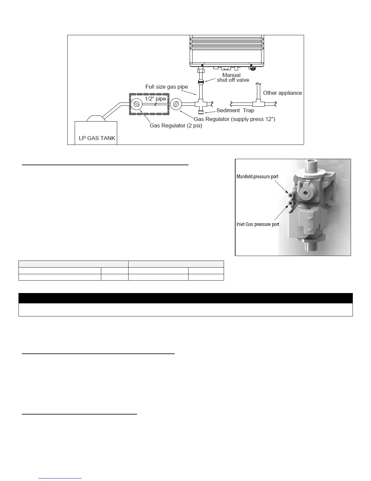
Figure 15 – LP Gas Piping Installation – NOTE: Capacity to be Not Less than Total Capacity of Connected Appliances
C. ADJUSTING GAS PRESSURE AT THE WATER HEATER
NOTE: Refer Figure 16 when adjusting gas pressure. Loosen the bolts before
checking the gas inlet pressure.
1. The water heater and its individual shutoff valve must be disconnected from the
gas supply piping system during any pressure testing of the system at test pressures
greater than ½ psi (3.5 kPa).
2. The water heater must be isolated from the gas supply piping system by closing its
individual manual shutoff valve during any pressure testing of the gas supply piping
system at test pressures equal to or less than ½ psi (3.5 kPa).
The minimum and maximum inlet gas line pressures must meet the requirements
shown in Table 15.
Table 15 – Gas Pressure Requirements
Do not fire (operate) the water heater until all connections have been completed and the heat exchanger is filled with water. Doing so
will damage the water heater and void the warranty.
PART 8 – WATER PIPING
A. GENERAL PLUMBING CONNECTION GUIDELINES
Pipe material must be suitable to meet local codes and industry standards.
The pipe must be cleaned and without blemish before any connections are made.
Do not apply a torch within 12” of the bottom connections of the water heater. Doing so could damage the water heater. Such
damages ARE NOT covered by product warranty.
The size of the hot water pipe should be ¾” diameter.
Isolation (shutoff valves) should be used to ease future servicing.
All piping should be insulated.
B. INSTALL A BACKFLOW PREVENTER
It may be recommended to use a back flow preventer – check local codes. If a back flow preventer or a no return valve is used, a
thermal expansion tank must be installed on the cold water supply between the water heater and valve.
Figure 16 – Inlet Gas Pressure Port Detail