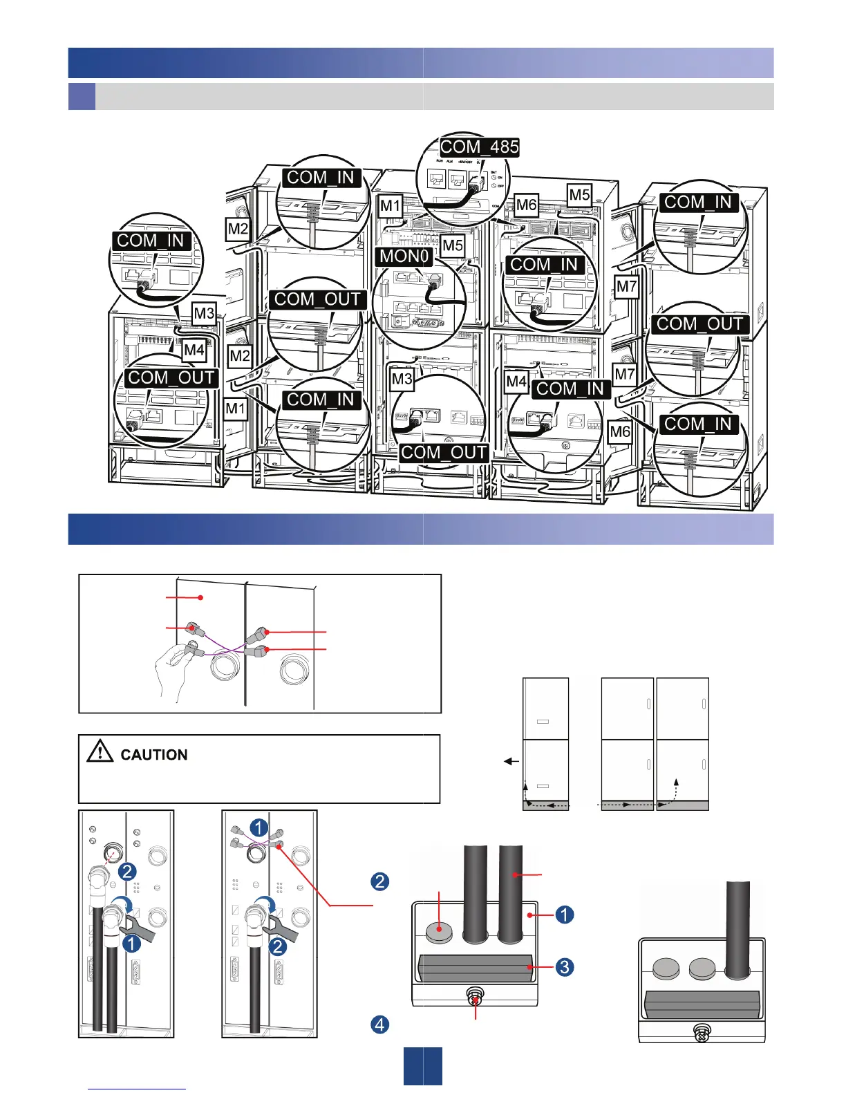
3 Installing the Monitoring Signal Cabl
AC Power Supply Scenarios
b
4. Scheme 4:2 APM30H + 2 RFC + TMC11H
4 Connect the RFU Cables
1. (Optional) Connect inter-RFU RF signal ca
RFU
RX_IN
RX_OUT
Inter-RFU
RF signal
cable
4. Connect the RF jumper.
During the installation, do not rotate the DIN male elbow
connector. This prevents any damage to the connector.
Or
Inter-
RFU RF
signal
1
Tight
4 IBBS200D (IBBS200T)
ble.
2. Add the DIN connectors to the RF
jumpers.
3. Route the RF jumper through the
base into the RFC.
For details, see the instruction guide contained in
the DIN connector package.
Ensure that the DIN male elbow connector is
perpendicular to the RFU.
Front
RFC RFC
or
Attach the color rings see
nstall the seal modules for the RF jumpers.
er cap
Or
RF Jumper
Install the seal
modules.
3
Insert
the
metal
chip,