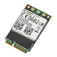
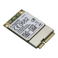
HUAWEI ME906s LTE M.2 Module
Hardware Guide
Huawei Proprietary and Confidential
Copyright © Huawei Technologies Co., Ltd.
Contents
1 Introduction.................................................................................................................................... 7
2 Overall Description ...................................................................................................................... 8
2.1 About This Chapter ........................................................................................................................... 8
2.2 Function Overview............................................................................................................................ 8
2.3 Circuit Block Diagram ....................................................................................................................... 9
3 Description of the Application Interfaces .............................................................................. 11
3.1 About This Chapter .......................................................................................................................... 11
3.2 75-pin Gold Finger........................................................................................................................... 11
3.3 Power Interface .............................................................................................................................. 19
3.3.1 Overview ................................................................................................................................ 19
3.3.2 Power Supply 3.3V Interface ................................................................................................. 19
3.3.3 USIM Power Output USIM_PWR .......................................................................................... 21
3.4 Signal Control Interface .................................................................................................................. 21
3.4.1 Overview ................................................................................................................................ 21
3.4.2 Power_On_Off Control Pin .................................................................................................... 23
3.4.3 RESET# Pin .......................................................................................................................... 28
3.4.4 LED# Pin ............................................................................................................................... 30
3.4.5 W_DISABLE# Pin .................................................................................................................. 30
3.4.6 GPS_DISABLE# Pin .............................................................................................................. 31
3.4.7 Wake_On_WWAN# Pin ......................................................................................................... 32
3.4.8 BodySAR_N Pin .................................................................................................................... 32
3.4.9 USIM_DET Pin ...................................................................................................................... 33
3.5 USB Interface ................................................................................................................................. 35
3.6 USIM Card Interface ...................................................................................................................... 36
3.6.1 Overview ................................................................................................................................ 36
3.6.2 Circuit Recommended for the USIM Card Interface .............................................................. 37
3.7 Tunable Antenna Control ................................................................................................................ 38
3.8 Config Pins ..................................................................................................................................... 39
3.9 Reserved Pins ................................................................................................................................ 40
3.10 NC Pins ........................................................................................................................................ 41
3.11 RF Antenna Interface.................................................................................................................... 41
3.11.1 RF Connector location ......................................................................................................... 41

 Loading...