EasyManua.ls Logo

Huawei ME909 Series - Page 14

Huawei ME909 Series
82 pages
To Next Page IconTo Next Page
To Previous Page IconTo Previous Page
Loading...
HUAWEI ME909 Series LTE LGA Module
Hardware Guide
Description of the Application Interfaces
Issue V0.3 (2013-05-21)
Huawei Proprietary and Confidential
Copyright © Huawei Technologies Co., Ltd.
14
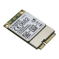
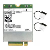
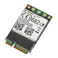
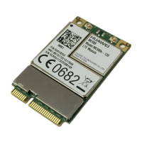
Figure 3-2 Appearance of ME909 series module (without label)
Table 3-1 shows the definitions of pins on the 145-pin signal interface of the ME909
module.
Table 3-1 Definitions of pins on the LGA interface
PIN
No.
Pin Name
I/O
Description
DC Characteristics (V)
Normal
MUX
Min.
Typ.
Max.
1
UART1_TX
-
O
UART1 transmit output
0.3
1.8
2.1
2
UART1_RTS
-
O
UART1 Ready for
receive
0.3
1.8
2.1
3
UART1_CTS
-
I
UART1 Clear to Send
0.3
1.8
2.1
4
UART1_RX
-
I
UART1 receive data
input
0.3
1.8
2.1
5
PCM_SYNC
-
O
PCM interface sync
0.3
1.8
2.1
6
PCM_DIN
-
I
PCM interface data in
0.3
1.8
2.1
7
PCM_DOUT
-
O
PCM interface data out
0.3
1.8
2.1
8
PCM_CLK
-
O
PCM interface clock
0.3
1.8
2.1
9
Reserved
-
-
Reserved, must keep
this pin open
-
-
-
10
Reserved
-
-
Reserved, must keep
this pin open
-
-
-
11
WAKEUP_IN
-
I
Host to set the module
into sleep or wake up
the module from sleep.
0.3
1.8
2.1
12
VBAT
-
P
Power supply input
3.3
3.8
4.2
13
VBAT
-
P
Power supply input
3.3
3.8
4.2

Table of Contents

Related product manuals