Installation Manual
Quidway R2600/3600 Series Modular Routers
Chapter 8
Function Modules
8-39
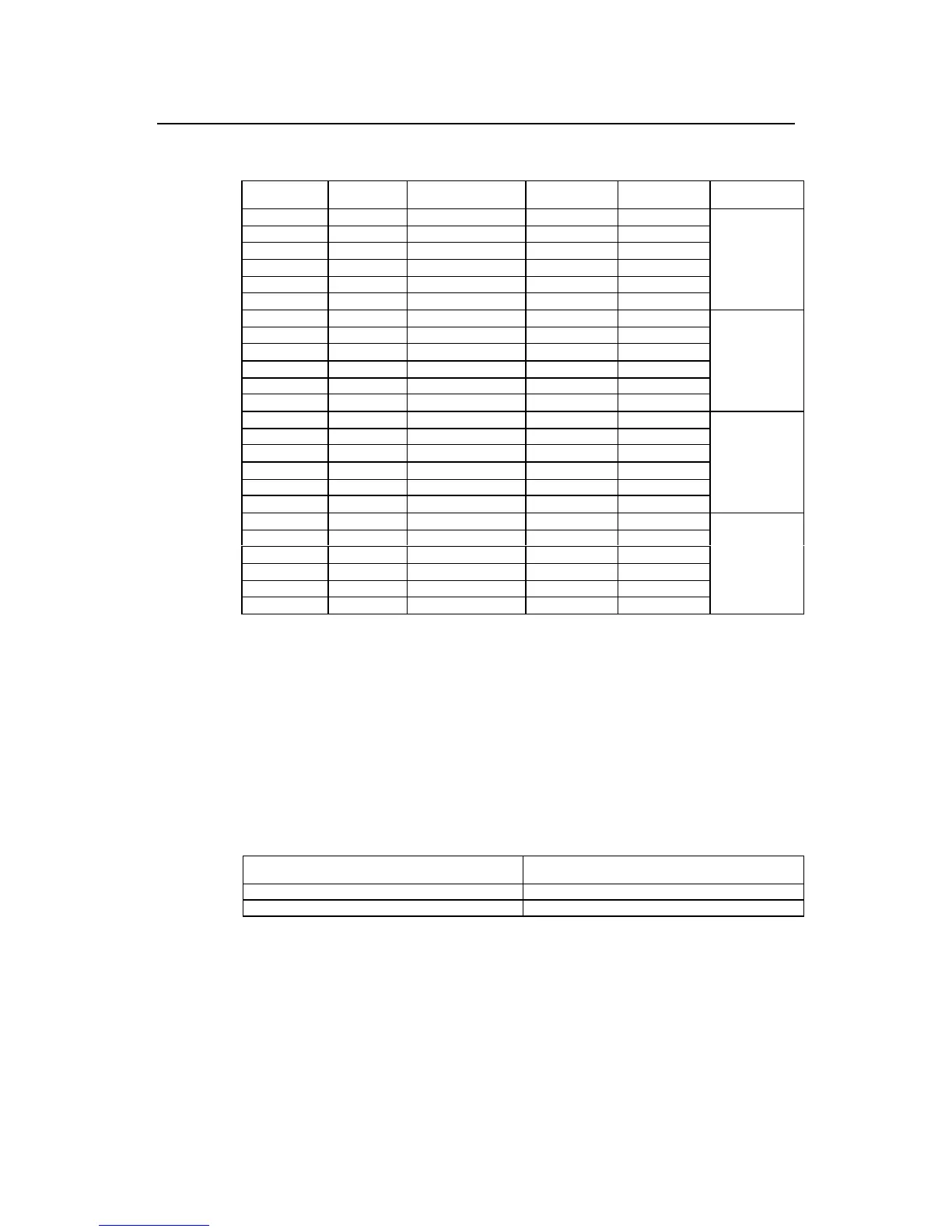
Table 8-25 4E1 cable pinouts
DB-25 Signal Direction of signal DB-15 Signal Remark
2TxR4
→
2TxRing
16 RxSD4 - 7 RxShield
14 RxT4
←
8RxTip
1TxT4
→
9TxTip
3TxSD4- 10TxShield
15 RxR4
←
15 RxRing
Channel 3
0TxR3
→
2TxRing
19 RxSD3 - 7 RxShield
17 RxT3
←
8RxTip
4TxT3
→
9TxTip
6TxSD3- 10TxShield
18 RxR3
←
15 RxRing
Channel 2
0TxR2
→
2TxRing
22 RxSD2 - 7 RxShield
20 RxT2
←
8RxTip
8TxT2
→
9TxTip
10 TxSD2 - 10 TxShield
21 RxR2
←
15 RxRing
Channel 1
12 TxR1
→
2TxRing
25 RxSD1 - 7 RxShield
23 RxT1
←
8RxTip
11 TxT1
→
9TxTip
13 TxSD1 - 10 TxShield
24 RxR1
←
15 RxRing
Channel 0
8.8.6 Internal DIP Switches
1E1/2E1/4E1 module provides internal DIP switches, and the setting of the DIP
switches decides the impedance and grounding mode of the connected cable.
z 1E1module DIP switch
z
The corresponding relations between 2E1 module DIP switches (S1 and S2) and
E1 interfaces are shown in the following table.
Table 8-26 Corresponding relations between DIP switches and E1 interfaces (2E1 module)
DIP switch Corresponding E1 interface
S1 Interface 0
S2 Interface 1
z The corresponding relations between the 4E1 module DIP switches (S1, S2, S3
and S4) and the E1 interfaces are shown in the following table.
 Loading...


