8
Plug insert
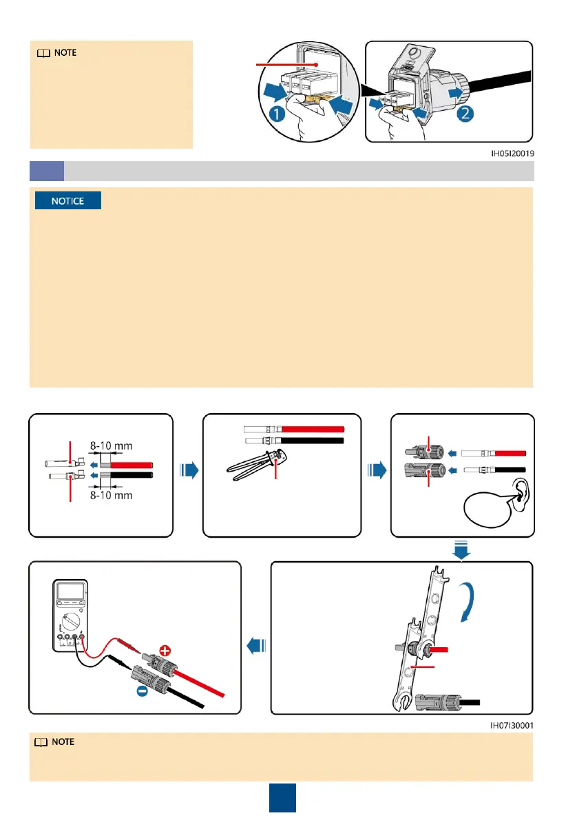
To remove the AC connector,
perform the operations in
reverse order of installing the
AC connector. Then, remove
the plug insert, as shown in
the following figure.
Installing DC Input Power Cables
3.5
1. Ensure that the PV module output is well insulated to ground.
2. Use the Staubli MC4 positive and negative metal terminals and DC connectors supplied with
the solar inverter. Using incompatible positive and negative metal terminals and DC connectors
may result in serious consequences. The caused device damage is not covered under warranty.
3. The DC input voltage of the solar inverter must not exceed maximum input voltage.
4. Before installing DC input power cables, label the cable polarities to ensure correct cable
connections.
5. If DC input power cables are reversely connected, do not operate the DC switch as well as
positive and negative connectors immediately. Failing to do so may cause device damage,
which is not covered under warranty. Wait until the solar irradiance declines at night and the
PV string current reduces to below 0.5 A, and then turn off the DC switch and remove the
positive and negative connectors. Correct the string polarity before reconnecting the PV string
to the solar inverter.
1. Assemble DC connectors.
Click
Positive metal terminal
Negative metal terminal
Ensure that the cable cannot
be pulled out after being
crimped.
Positive connector
Negative
connector
Use the wrench shown
in the figure to tighten
the locking nut. When
the wrench slips during
the tightening, the
locking nut has been
tightened.
Ensure that cable
polarities are correct.
PV-CZM-22100/19100
PV-MS-HZ
Open-end wrench
If the PV strings are configured with Smart PV Optimizers, refer to the
Smart PV Optimizer
Quick Guide
to check the cable polarity.
 Loading...