Voltage
Thresholds
Volt Threshold
Min LN1
–30% to –5%
The step increase is ±1%. The
default settings are –10% for LN1
and LN2. Set the parameter
based on site requirements.
Volt Threshold
Min LN2
–30% to –5%
Volt Threshold
Max LN1
+5% to +30%
The step increase is ±1%. The
default settings are +10% for LN1
and LN2. Set the parameter
based on site requirements.
Volt Threshold
Max LN2
+5% to +30%
Frequency
Thresholds
Freq Threshold
Min LN1
–10% to –1%
The step increase is ±1%. The
default settings are –5% for LN1
and LN2. Set the parameter
based on site requirements.
Freq Threshold
Min LN2
–10% to –1%
Freq Threshold
Max LN1
+1% to +10%
The step increase is ±1%. The
default settings are +5% for LN1
and LN2. Set the parameter
based on site requirements.
Freq Threshold
Max LN2
+1% to +10%
Modbus • Modbus address
• Modbus baud rate
• Modbus stop bit
• Modbus parity check
• Local / Remote
Set the parameter based on site
requirements.
Language Chinese; English; Deutsch;
Francais; Itatiano; Espanol;
Suomi; Russian
Set the parameter based on site
requirements.
PDC Silk Screen Description
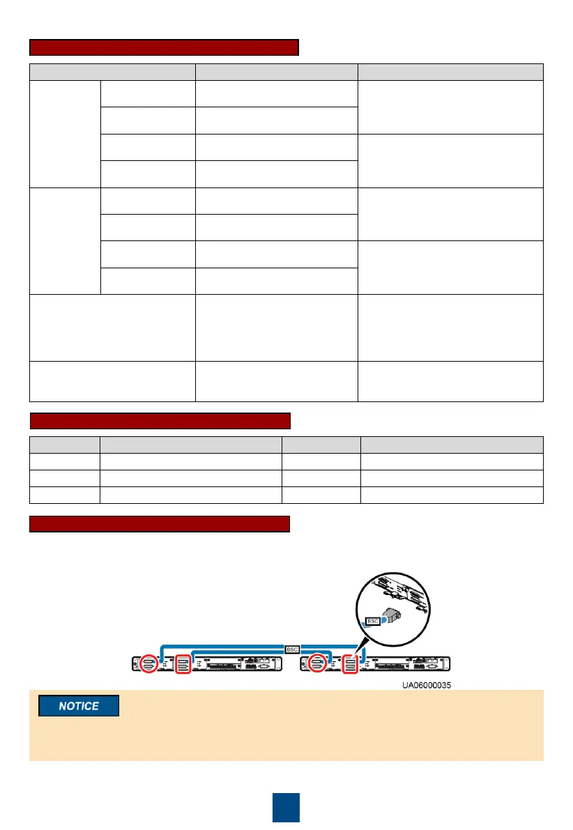
Introduction to BSC Connection
In a dual-bus (2N) system, connect BSC cables to the master and slave systems, as shown in the
following figure.
The BSC port is used in a dual-bus system to synchronize output frequencies and phases
between UPS systems, ensuring that two buses can switch with each other.

 Loading...