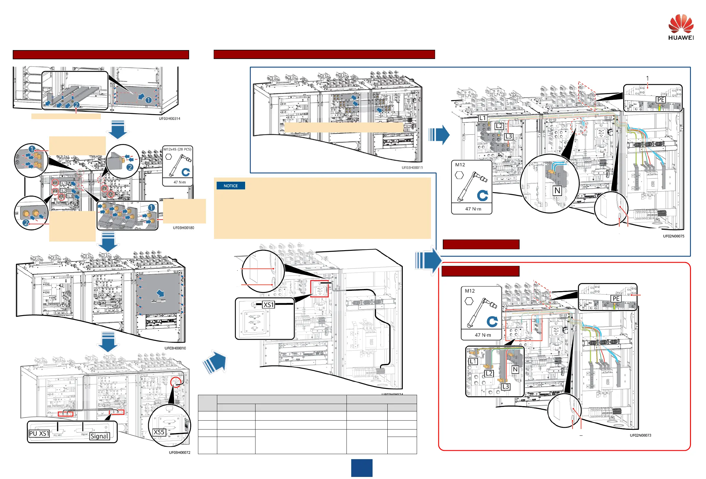
Install screws on battery
copper bars at the
combination position.
Install screws on
output copper bars
at the combination
position.
Remove the screws
preinstalled on
copper bars and
install parallel
copper bars.
6
Installing Copper Bars and Signal Cables inside the UPS Cabinet
Remove parallel copper bars.
Signal cable hole
Power cable hole
Copper bars are heavy. Two persons are required.
Power cable hole
Signal cable hole
Power cable hole
Signal cable hole
Side view of the UPS
Side view of the UPS
Different Power Sources
Single Power Source
Installing Power Cables between the UPS and the Inductor Cabinet (1600 kVA)
Position of Wiring Terminal 1
Position of Wiring Terminal 2
One end of the NTC cable and inductor
cable is preinstalled. The other end is
reserved inside the cabinet and needs to
be connected to the bypass cabinet.
• Cables have been preinstalled and bound in the inductor cabinet.
• The cables from the inductor cabinet to the UPS are configured based on the longest cable
length before delivery. If short cables are needed in the actual installation scenario, you can
cut the excess cables and crimp terminals.
• Cables must be bound to the nearest beam or cable bridge according to the route shown in
the figure.
• Do not bind signal cables and power cables together.
• The number and colors of cables in the figures are for reference only.
UPS5000-H-(1200 kVA-1600 kVA) Quick Guide (100 kVA Power Modules, Three-Phase Three-Wire)

 Loading...