Do you have a question about the Humminbird Wide Optic and is the answer not in the manual?
Lists included components for fishfinder installation.
Details available accessories to enhance fishfinder capabilities.
Provides a summary of the fishfinder installation process.
Explains options for mounting the transducer on the boat hull.
Details alternative transducer types and their specific mounting methods.
Adapts transducer for portable use with suction cup.
Explains mounting transducer on trolling motors using an accessory kit.
Details installing transducers through the hull of the boat.
Information on exchanging the standard transducer for other types.
Lists additional tools and parts needed for installation.
Guides on selecting the optimal location on the transom for mounting.
Instructions for drilling holes for the transducer mounting bracket.
Details on assembling the transducer to its mounting components.
Steps for attaching the assembled transducer to the boat transom.
Guidance on adjusting the transducer's angle and height for optimal performance.
Instructions for routing the transducer cable through the boat.
How to choose the best spot inside the hull for transducer placement.
Performing a trial installation to check performance before permanent mounting.
Steps for securely attaching the transducer inside the hull with epoxy.
Guidance on selecting the best location for the control head.
Steps for wiring the control head to the boat's power supply.
Instructions for drilling holes for the control head mounting bracket.
How to route all necessary cables to the control head location.
Details on connecting and mounting the cable connector holder.
Explains how to use the simulator mode for learning.
How user settings are retained or lost in simulator mode.
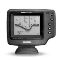
Describes the default display when Temp/Speed sensor is or isn't installed.
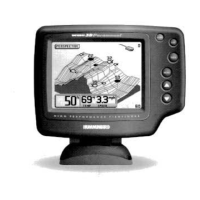
Explains the display when a Wide Side transducer is connected.
How bottom composition affects the on-screen graphic representation.
How to identify and interpret objects attached to the bottom.
Explains different sonar targets, thermoclines, and fish symbol meanings.
Overview of the 5-button keypad and input confirmation.
Functionality of the POWER and LIGHT buttons for unit operation.
Explains how the menu navigation buttons control user functions.
How to adjust receiver sensitivity and noise filtering.
Controls the vertical display range for water depth.
How to enlarge specific areas of the water column for detail.
Setting an audible alarm for shallow water depths.
Alerts the user to detected fish targets.
Records and displays trip data like speed, distance, and voltage.
Accesses a series of user preference settings for customization.
Selects units of measurement for speed (MPH, KTS).
Controls how fish targets are displayed and interpreted.
Adjusts the size of digital readouts on the display.
Selects or identifies the connected transducer type.
Controls the rate of graphic information movement on screen.
Returns all user settings to factory defaults.
Enables a diagnostic tool to identify unit problems.
Discusses compatibility with different transducer types.
Details the multi-element sonar and beam coverage of the Wide Side transducer.
| Sonar Type | Dual Beam |
|---|---|
| GPS | No |
| Water Resistance | Yes |
| Display Size | 5 inches |
| Sonar Frequency | 200 kHz |
| Depth Capability | 600 ft |
| Beam Angle | 20° |