Do you have a question about the Humminbird WIDE Paramount 3D and is the answer not in the manual?
Lists all components included in the Humminbird fishfinder package.
Describes the two primary components to install: control head and transducer.
Explains options for mounting the transducer on the transom or inside the hull.
Details alternative mounting options like portable, trolling motor, and thru-hull.
Lists necessary tools and materials required for installation.
Guidelines for selecting the optimal position on the boat's transom.
Step-by-step instructions for drilling holes for the transducer mount.
Assembling the transducer with its mounting hardware.
Securing the assembled transducer to the transom.
Fine-tuning the transducer's angle and height for optimal performance.
Instructions for routing the transducer cable through the transom into the boat.
Guidelines for finding the best spot inside the boat's hull for the transducer.
Performing a trial installation to verify the transducer's mounting position.
Final steps for securing the transducer inside the hull using epoxy.
Selecting the best position for the fishfinder's control unit.
Wiring the control head to the boat's power source.
Drilling pilot holes for the control head mounting bracket.
Routing cables and securing the mounting bracket for the control head.
Connecting cables to the unit via the connector holder and mounting it.
Verifying the correct operation of the installed fishfinder.
Instructions on using the simulator mode for learning features.
Overview of the information presented on the fishfinder's display screen.
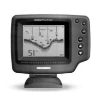
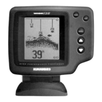
Explains the standard two-dimensional sonar view and its data.
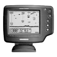
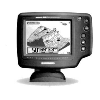
Describes the combined 3D and 2D sonar view for enhanced analysis.
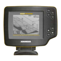
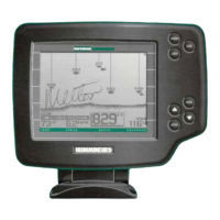
Details the three-dimensional sonar view and its graphical representation.
How the display graphically represents the bottom's composition and texture.
Factors affecting sonar signals like wave action and thermoclines.
How to turn the unit on/off and access simulator mode.
Controls for adjusting display and keypad backlight brightness.
Toggles between different screen display configurations (views).
Using buttons to navigate menus and make adjustments.
Controls the sonar receiver's sensitivity to detect weaker signals.
Sets the vertical distance displayed on the sonar screen.
Magnifies specific areas of the sonar display for detailed viewing.
Configures an audible alarm for shallow water conditions.
Sets up audible alerts for detected fish targets.
Logs and displays trip data like distance, speed, and elapsed time.
Allows changing the viewpoint for terrain display in 3D or Combo modes.
Controls the LCD display's contrast level for better readability.
Sets the preferred units for speed display (MPH or KTS).
Configures how the unit interprets and displays fish targets.
Adjusts the size of digital readouts on the display.
Selects the type of transducer connected to the unit.
Adjusts the rate at which sonar graphics move across the screen.
Sets how long menus remain visible after the last button press.
Adjusts the depth measurement reference point on the boat.
Compensates for speed measurement discrepancies due to hull design.
Controls the display of sonar beam width information.
Allows hiding seldom-used menus from the main sequence.
Restores all user-configurable settings to their default values.
Accesses a diagnostic tool to check unit operation and connections.
Interpreting results from the unit's self-test and connection checks.
Using a specialized transducer for deep water fishing.
Utilizing a side-looking transducer for bank and open water fishing.
Explains the different views available when using the Wide Side transducer.
| 3D Sonar | Yes |
|---|---|
| Transducer | Included |
| GPS | No |
| Mapping | No |
| Networking | No |
| Sonar Coverage | 90° total coverage |
| Sonar Type | 3D |
| Frequency | 200 kHz / 455 kHz |
| Power Output | 500 Watts (RMS) |
| Mounting Type | Gimbal |
| Display Size | 5 inch |