unter 50cc • AC Electric S
stems
.
Be certain the water heater is full of water and does
not contain air. If the water heater is not full of wa-
ter, dama
e to the heatin
elements ma
result when
the electrical
ower is turned on to the unit
Fi
.
.
ives
ou a look at the shore power connection
n the transom o
our boat.
Shown is the aft shore
ower connection
Later on in this section, we will detail the steps to con-
nectin
our shore power. Lets take a look at more of the
shore power components.
.1.2 Shore Power Cord
We have supplied
ou with a durable 50’ shore power
r
.
r
w
v
m
nn
t
n
n
n
n
n
m
l
nn
ti
n
n th
th
r
n
. D
n
t
hemicals to clean or service
our shore power cord,
unless specified b
the manufacturer. Follow the manu-
acturer’s recommendations on servicin
or cleanin
our
shore power cord.
.1.3 Isolation Transforme
e
on
t
e s
ore power connect
on an
t
e s
ore
power breaker,
our A
power will be routed throu
h the
Isolation Trans
ormer.
ee the Mechanical Arran
ement
Ill
tr
ti
n f
r th
l
ti
n
f th
I
Tr
n
f
rm
r
The I
Trans
ormer is a standard
dr
” t
pe 12 KVA
transformer that basicall
isolates
our boat from the
shore power. It is a valuable sa
et
eature aboard
our
t.
.1.4 Distribution Panel
MDP
ere is a look at the distribution panel installed on
our
boat. The distribution
anels for both AC and DC
ower
r
l
t
hin
th
n
v
t
ti
n
t.
The
enerator is a diesel powered en
ine, so there are
some safet
rules for an
t
pe of fuel en
ine. Lets look at
some instructions o
the wired remote control panel and
ou can find more details on the
enerator’s instruction
m
n
.
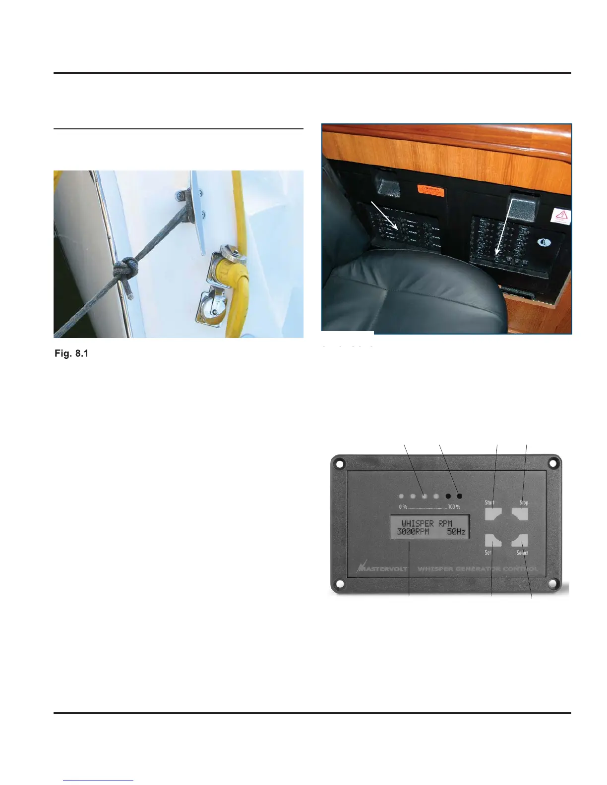
Generator Control Panel
1 2 6 5
347
1
tart button;
2 Stop button;
elect button
4
et button;
a
ure
amp;
enerator load indicator.
7 Displa
AC Panel
DC Panel
Fi
. 8.2