nt
r
C
• D
Electric
7.5
7.2 S
stems and Components
There are man
s
stems and components on the D
side
f
our boat from emer
enc
and safet
to entertainment.
These s
stems make up the lar
est part of
our electrical
s
stem
ere we will discuss the electrical parts of those s
stems
and tr
and
ive
ou a better understandin
o
the uses
and features of
our DC electrical s
stems and compo-
nents. Since the lar
est part of
our controls are at the
DP, we will start there and run down the s
stems and
omponents as the
are listed on the MDP. From there,
we will look at the batter
switch panel, and finall
, the
h
lm
ntr
l
.
7.2.1 DC Main
In order to ener
ize the DC s
stem aboard
our boat,
ou
must turn the breaker marked “DC Main”, on the batter
switch panel, to the
n” position. This supplies power to
the remainin
breakers and s
stems on the distribution
ane
.
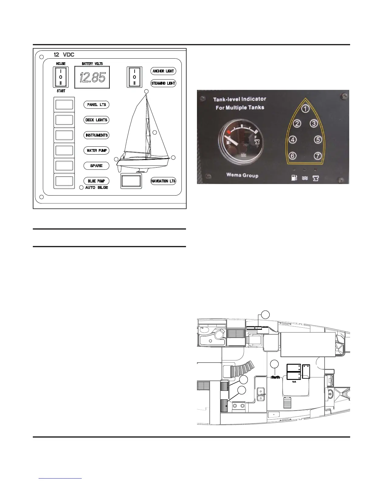
7.2.2 Water S
stems
The water s
stems are outlined in the Water S
stems
ha
ter in this manual. However, the controls an
monitors for these s
stems are all powered b
the DC
ectr
ca
s
stem.
The water tank monitor as shown in Fi
. 7.4 allows
ou
to se
ect t
e tan
to mon
tor t
e water
eve
n t
e res
ec-
tiv
t
nk.
The power switch turns the monitor on, then
se
ect t
e tan
ou want to mon
tor.
e
au
e on
the le
t will show the amount remainin
in the tank.
The waste tanks are also monitored from this location b
selectin
numbers six, or seven
rom selector switch
1
n Fi
. 7.4.
7.2.3 Refri
erato
The breaker marked “refri
erator”, on the main breaker
panel behind navi
ation station access panel, supplies
power to the DC powered refri
erator aboard
our boat.
ee Fi
. 7.5 for the arran
ement la
out of this s
stem.
1
2
3
4
+
+
+
1. REFRIGERATOR
2. FREEZER
3. DC CONTROL PANEL
4. BATTERY SELECT SWITCH
Fi
.7.3
Fi
.7.4
Fi
.7.5