nt
r
C
• D
Electric
7.
The batter
switch panel houses the breakers for some
f the main components in
our DC s
stem. The breaker
ontrols are marked at the switch panel, and control s
s-
tems or components on
our boat that require a connec-
t
on t
at rema
ns ener
ze
even t
rou
t
e
a
n
ane
ma
be de-ener
ized
e
rea
ers an
sw
tc
es are
escr
e
n
reater
eta
in the
Breakers and
witches” section o
this chapter
7.1.3 Batter
Char
in
S
ste
efer to the power suppl
locator drawin
Fi
. 7.1
at
the be
innin
of this section for the location of the batter
har
er. The char
er is protected b
a
use on the posi-
tive and
round side at the char
er.
o operate the char
er, ensure that it is operatin
onnect the shore
ower cord to the shore
ower
inl
t
n th
t
rn
th
t
n th
t
.
i
. Th
n t
the dockside suppl
.
Turn on the A
Main breaker, located in the a
t cabin
Turn on the Batter
Char
er switch on the control
panel.
7.1.5 Breakers, Switches, and Fuse
All electrical s
stems aboard
our boat are provided with
ver-current
rotection in the form of breakers or fuses.
xamples o
breakers are the s
stem or component con-
trols at the Main Distribution Panel, or MDP, or in the bat-
ter
selector switch panel. S
stems that would normall
require
ou to ener
ize them for use are provided with
w
t
.
The breaker and switch panels are detailed
ur-
ther in the end of this section under “Le
ends.
7.1.7 Generator
Option
Althou
h, technicall
, the
enerator is part o
the A
stem, because it supplies A
power, the startin
o
the
enerator requires DC power. The
enerator startin
receives power
rom the start batter
bank
The
enerator supplies 120/240, volt 60 hz AC power for
peratin
devices and equipment controlled throu
h the
A
control panel
Main Distribution Panel, MDP
When the
enerator indicatin
li
ht is on and the
enera-
tor breakers are on, A
power is supplied to A
control
ane
ev
ces an
e
u
ment.
e
er to the
peration and Procedures” part o
the A
lectric section for information on startin
the
enerator.
You can
ind or locate the
enerator and all the respective
omponents usin
the Generator S
stem Drawin
at the
nd o
this chapter.
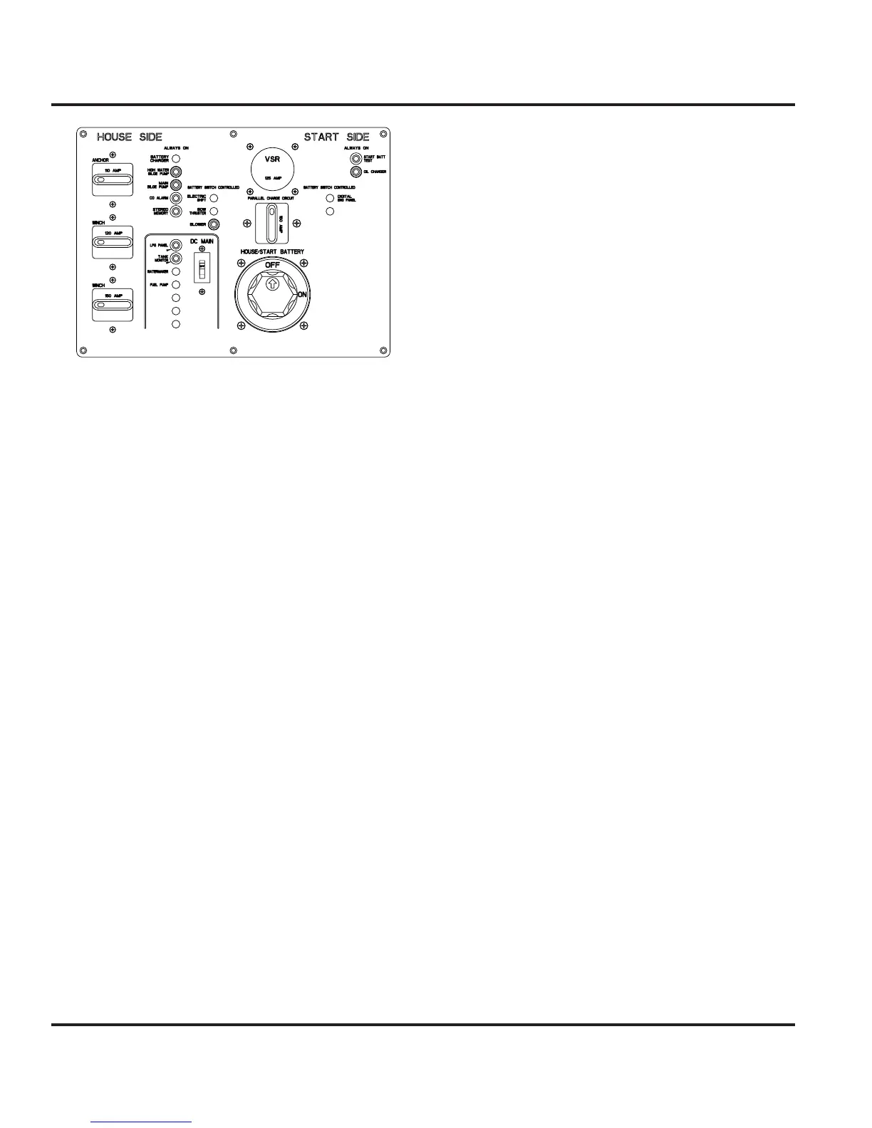
7.1.8 Main Control Panel
DC Side
You can view the parts o
the D
side o
the main control
panel here
Fi
. 7.3
. Notice the batter
selector switch at
the top le
t, when switched on the respective volta
e o
the batter
is shown on the ri
ht b
the di
ital volt meter.
n
cator
ts are
u
t
nto most sw
tc
es an
a
ert
ou
that the selected s
stem is powered.
e
str
ut
on pane
s out
ne
n t
e
e
en
s sect
on
this chapter.
efer to the “
perations” section of this chapter to view
instructions on how to ener
ize the separate s
stems on
our boat.
Fi
.7.2