nt
r
CC
nderwater
ear
6.2
nderwater Gear
Your underwater Gear consists of the followin
ropulsion components
sail drive and bow thruster
teerin
components
eawater Intake, and dischar
e skin
ittin
s
onitorin
Equipmen
6.1 Mechanical Pro
ulsion Com
onents
DANGER
! !
eep clear of movin
parts at all times. Protect
ovin
parts from access durin
normal use.
ropulsion components are an
component that would
be involved in the movement of
our boat.
6.1.1 Propeller
e prope
er supp
e
w
t
our
oat
as
een se
ect-
d as the best propeller
or avera
e use. Propellers
use “pitch” or the an
le of the blades to determine
the amount of power exerted from
our en
ines. Do
not chan
e the pitch o
our propellers without
et-
tin
our dealers recommendations first. If
ou chan
e
to a different
ro
eller
itch, under no circumstances
use a propeller which allows the en
ine to operate
at a hi
her than recommended RPM. Your en
ine
manual will specif
the maximum recommended RPM.
To maintain rated power, propellers should be free o
n
c
s, excess
ve p
tt
n
an
an
stort
ons t
at a
ter t
em
rom their ori
inal desi
n. Badl
dama
ed propellers
should be replaced, but those that are chipped, bent or
merel
out of shape can be reconditioned b
our marine
l
r.
6.1.2 Pro
eller Shaf
The propeller sha
t is made o
Aquamet 19 or equivalent
t
n
t
w
x
nt
rr
n r
t
n
and ver
hi
h stren
th. The couplin
at one end o
the
h
t i
lt
t
th
tr
n
mi
i
n. Th
th
r
n
th
shaft is tapered, threaded, and ke
ed for installation o
the propeller. The propeller sha
t passes throu
h the hull
ncased in the sha
t lo
.
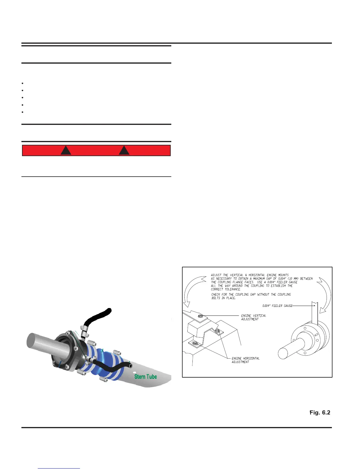
6.1.3 Ali
nmen
Ali
nin
the en
ine with the propeller sha
t is critical
or
smooth operation of
our boat. Shaft ali
nment ma
han
e sli
htl
a
ter
our boat is in use. Your dealer
should check ali
nment as part o
commissionin
, par-
ticularl
if there is vibration, a drummin
sound, or loss
RPM’
.
Below is an illustration showin
the steps for
ali
nment, however we recommend this prac-
tice be performed by competent professionals.
6.1.4 Struts
ach propeller sha
t is supported b
man
anese bronze
tr
t
t
n
t
th
tt
m
th
h
ll. Th
tr
t
h
v
replaceable bearings to minimize wear and to protect
the sha
t at the points where it passes throu
h the strut
Fi
. 6.
shows the ima
e of dripless stuffi n
box used
on
our boat