nt
r
C
• D
Electric
7.
7.2.4 Li
htin
S
stem
There are basicall
four different li
htin
s
stems aboard
our boat. These are the interior and exterior li
htin
,
the sa
et
and navi
ational li
htin
, and, i
supplied, the
ourtes
t
n
.
The interior and exterior li
htin
s
stems are separated
because of the method in which
ower is su
lied to the
two s
stems. The interior li
hts are powered
rom the
DP and marked
abin Li
hts. The exterior li
htin
is
owered from the MDP and have switches on the main
ontrol panel
or their operation
The en
ine room area li
htin
are also powered from the
DP.
The next area, safet
and navi
ational li
htin
, closel
ollows
oast
uard re
ulations re
ardin
sa
et
and
navi
ational li
hts. The
are as
ollows
av Li
hts
teamin
Li
h
ast
eck Li
h
e re
an
reen
ts on t
e
ow ra
an
t
e w
te
acin
li
ht on the transom are known as
Nav Li
hts”.
These li
hts should alwa
s be on when motorin
.
The
steamin
” li
ht is the
orward
acin
li
ht mounted
hal
wa
up the mast. This should be on when underwa
w
t
sa
power on
The anchor li
ht is a 360
li
ht mounted at the top
f the mast and should onl
be on when anchored.
The en
ine area li
htin
is controlled b
the courtes
li
ht
breaker, and the Deck li
ht
ives li
htin
to the foredeck
.
Li
htin
circuits and locations are outlined in the end o
this chapter.
7.2.5 CO Monitors
In each area aboard
our boat,
ou will
ind a
Monitor
Carbon Monoxide Monitor
. We care about
our safet
and have installed these
Monitors to show our con-
ern. For more in
ormation about the
Monitors
mounted on
our boat, consult
our owner
s packet and
find the documentation for the
Monitors.
7.2.6 Entertainment Centers
The entertainment centers in the berthin
areas of
our
boat are 12 volt D
powered. The power is supplied
throu
h the distribution panel. The television is A
pow-
red from a DC to AC inverter, and the stereo is DC
powered. More in
ormation about the controls o
our
ntertainment centers and equipment can be
ound in
our owner
s packet.
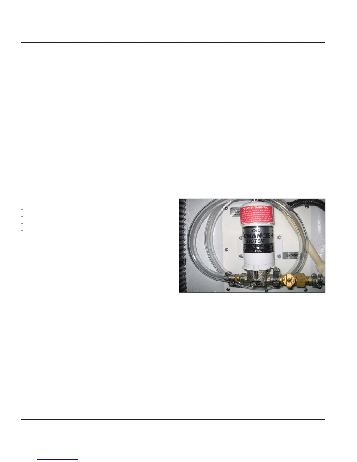
7.2.7 Oil Chan
er
Option
Your boat ma
be equipped with the optional oil chan
er.
The oil chan
er receives its power
rom the D
Electrical
stem. The breaker is located on the Batter
Switch
anel. The breaker is marked
IL
HAN
ER.
onsult
our mechanical arran
ement for the location o
the oil chan
er.
Fi
.7.
Note: Discharge of oil is prohibited. The Federal Water
Pollution Control Act prohibits the discharge of oil or oily waste
into or upon navigable waters and contiguous zone of the
United States. If such discharge causes a film or sheen upon,
or discoloration of the surface of the water, or causes a sludge
or emulsion beneath the surface of the water, violators are sub-
ject to a penalty of $5,000.
7.2.10 Bil
e Pump S
stems
Your boat is equipped with 2 bil
e pumps and one emer-
enc
bil
e pump. For locations o
the bil
e pump s
s-
tems, consult
our Mechanical Arran
ement Drawin
or
the Sanitar
S
stems Drawin
The Bil
e Pump
stem consists o
a pump and a
loat