nt
r
C
• D
Electric
7.7
switch. When the water level rises far enou
h to activate
the float switch, this activates the
um
which lowers the
water level down to a point that the
loat switch stops the
power. Fi
. 7.10 shows
ou the t
pical wirin
For more information about
our bilge pump s
stem, see
anitar
stems
Battery Switch Panel
Main Distribution Panel
BATTERY TEST
PORT
STBD
DC DISTRIBUTION PANEL
12 VOLT D.C.
24V DC
12V DC
DC AMPS
START-STOP/PRIME
STATUS
Typical Bilge Pump Wiring Diagram
7.2.11 Ventilation
entilation is a ver
important issue with
our boat, with
the potential for Carbon Monoxide buildup
See Boatin
a
et
ection
, alon
with the simple com
ort o
resh
air or air conditionin
, ventilation is a standard that is a
necess
t
n
our boat, there are essentiall
three t
pes o
ventila-
tion, the air conditionin
s
stem
AC s
stem
, the blower,
and the Bomar hatches, which suppl
ou with
resh
air when opened.
ince the air conditionin
s
stem is
AC powered
see AC Electric Section
and the hatches
require no power, we will detail the blower
or
ans
, and
their
unction, here.
For blower location, consult
our Mechanical Arran
ement
illustration in the Boatin
a
et
ection, or the Ventilation
tr
t
n
n t
m
t
n.
WARNING
! !
Fuel fumes in the en
ine compartment can explode.
Before workin
on electrical wirin
, ventilate
en
ne room an
sconnect
atter
ca
es to
revent s
arks.
The en
ine room blower is an exhaust
an which will
remove an
exhaust
umes
rom the en
ine room, as well
as, remov
n
eate
a
r.
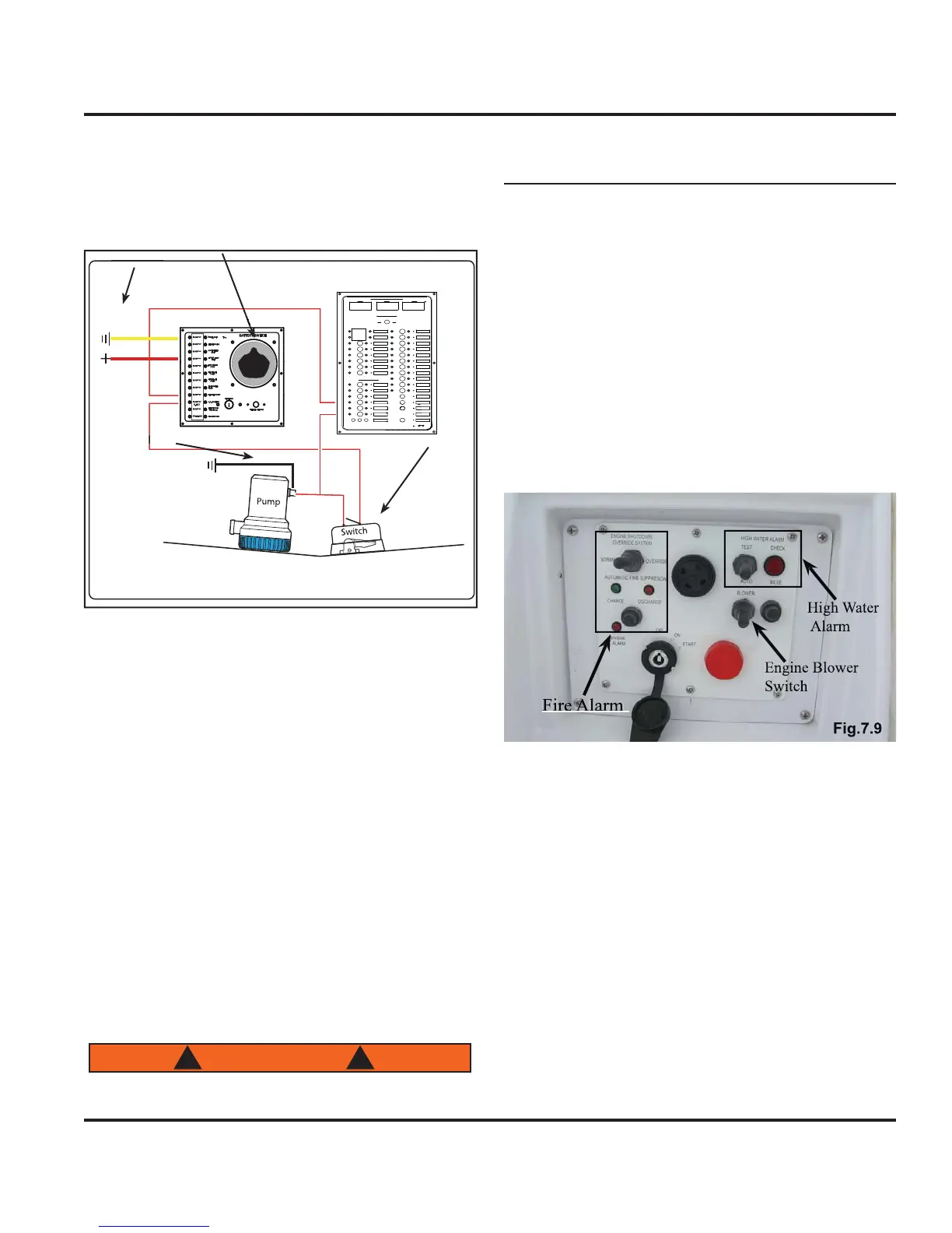
7.2.12 Fire Extin
uishin
S
stems
In the en
ine room, there is a
ire extin
uishin
bottle
installed. This s
stem is D
powered with the rela
, or
module”, and the alarm at the helm station.
When a
ire is detected on
our boat, the alarm will sound
and set off the Halon bottle. This rela
will shut down the
n
ines, the blowers, and the
enerator. To reset the
s
stem, activate the reset switch on the monitor at the
helm. See Fi
. 7.9
7.2.13 Shower Sum
The shower sump is part o
the
anitar
stem and
more information about the Shower Sum
can be found
in that section. However, the breaker control
or the
hower
ump can be
ound on the MDP
7.2.14 Windlas
our
oat ma
e equ
ppe
w
t
an opt
ona
w
n
ass.
t
receives its power
rom the D
electrical s
stem. The
windlass o
ers
ou the abilit
to raise and lower
our
anc
or.
ere
s a
so a c
rcu
t
rea
er at t
e
atter
switch. The windlass can be operated
rom the bow.
ee
manu
acturer’s owner’s manual about the proper and
safe operatin
procedures. See Fi
. 7.12
Batter
Switch
ower
TATU
Fi
.7.