unter 50cc • AC Electric S
stems
.
it run warm. Continuous load should be restricted to 70
m
xim
m l
.
Stoppin
enerator
1
witch o
all electrical devices
consumers
. I
th
eneratin
set has been runnin
under
ull load
or a
lon
er period, do not shut it down abruptl
. Reduce the
lectrical load to about 30
o
the rated load and let it run
or approx. 5 minutes
2 Press the
T
P button
lose the inlet sea water cock
4
witch to an other A
power source, i
available. I
a
ass
stemswitc
is installed, this is done automati-
all
.
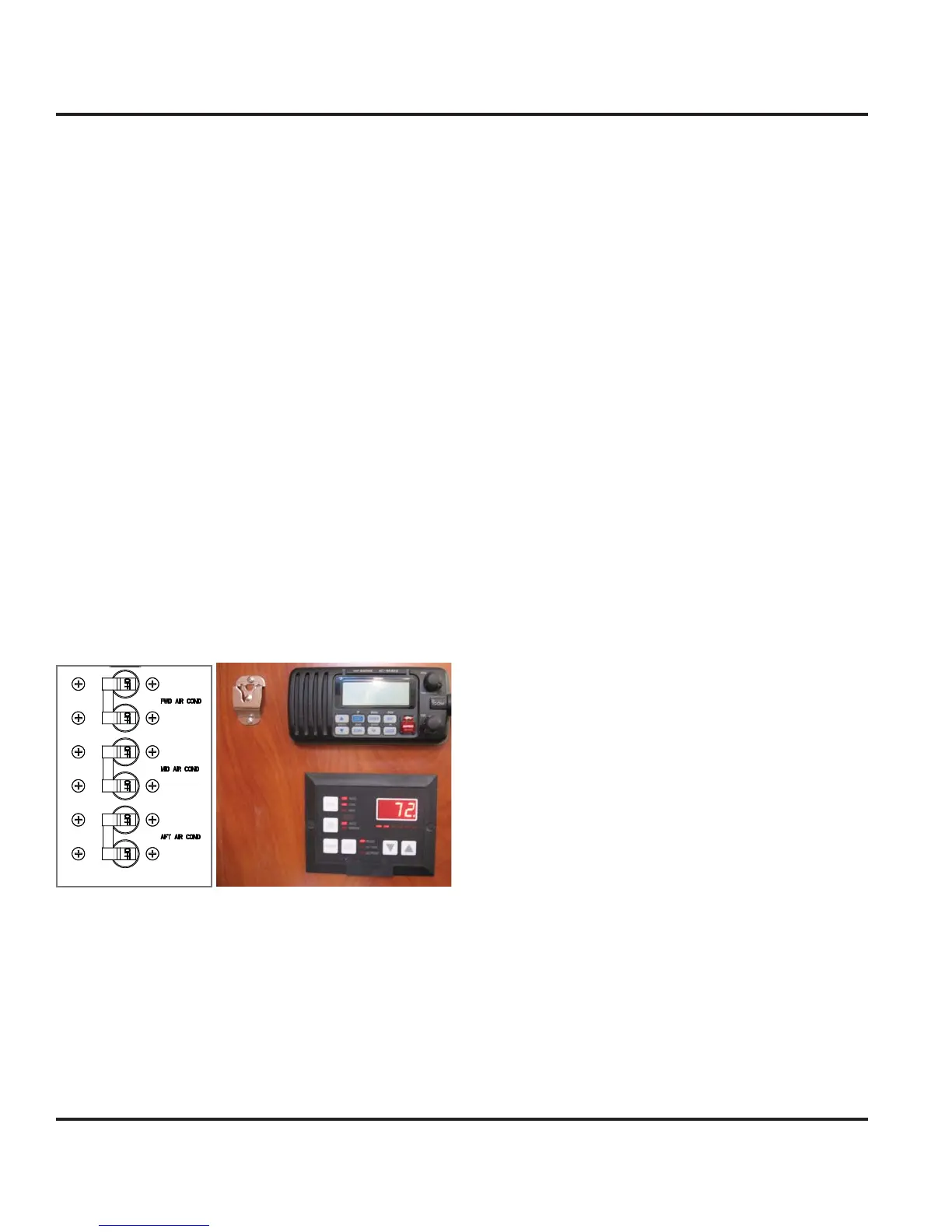
.3.6 The Air Conditionin
S
stem
Option
ere are t
ree a
r con
t
on
n
un
ts
nsta
e
on
our
boat. Ensure that
ou read the instructions on the air
onditioner’s owner’s manual
or more detail operatin
inf
rm
ti
n.
ig. 8.6 Air contioner breakers on AC control panel. the
r cond
t
oner control panel on ma
n cab
n nav
gat
on
tati
n
1. Ensure
ou have 240 volt
230 overseas
power to the
2.
heck to make sure that the seawater intakes, and
dischar
e for the A/C s
stem coolin
is open and that the
tr
in
r i
l
n
n
ri
r
. Ener
ize the Air Conditionin
s
stem at the MDP
ane
.
4.
heck to make sure that the dischar
e is
lowin
at the
Air Conditionin
coolin
water dischar
e.
General O
eration
The A
unit reverse c
cle air conditioner has both a
heatin
and coolin
mode of operation. It uses R-22
r R407c re
ri
erant in a conventional vapor compres-
sion c
cle to trans
er heat
rom the air in the boat to the
water.
n t
e coo
n
mo
e, a
ower
ows t
e ca
n a
r
throu
h the indoor or evaporator coil where it is cooled
and dehumidi
ied. Liquid re
ri
erant passin
throu
h the
vaporator is boiled into a
as b
heat removed from the
air. The warmed re
ri
erant
as enters the compressor
where its temperature and pressure are increased. The
hot refri
erant
as travels to the water coil or condenser
where it is cooled b
the water and condenses to a liquid
Liquid refri
erant is metered back into the evaporator coil
to repeat the process.
n the heatin
mod
the process is reversed. A spe-
ial reversin
valve reverses the flow of the refri
erant
throu
hout the s
stem exchan
in
the roles o
the con-
denser and evaporator. The re
ri
erant
lows throu
h the
water or evaporator coil, picks up heat from the water,
and becomes a vapor. The vapor then enters the com-
pressor w
ere
t
s compresse
to a
er temperature.
It is then pumped to the indoor coil where the air movin
across t
e co
c
s
t
e
eat an
t
e warm a
r
s
blown into the room. The compressed re
ri
erant vapor
ondenses to a liquid as it
ives up heat. Finall
, liquid
refri
erant flows into the capillar
tubes into the indoor
oil where the c
cle is repeated.
e reverse c
c
e a
r con
t
oner
s contro
e
a con-
troller mounted on the main cabin navi
ation station,
port side a
t en
ine bulkhead in a
t cabin and above port
han
in
locker in the forward cabin
l
r
r
t
ir
n
iti
n
r’
wn
r’
m
n
l
r
detail information re
ardin
operatin
of the A/C unit and
m
int
n
n
in
rm
ti
n.