Do you have a question about the Hydro Action AP-500 and is the answer not in the manual?
Steps for accessing the plant and enclosure upon arrival.
Procedure for collecting and testing sludge sample volume.
Checking for consistent air bubble turbulence in aeration.
Maintenance procedures for ensuring proper aeration.
Maintenance of the air pump inlet filter.
Monitoring air pressure at the Schrader valve.
Checking effluent color and odor for proper quality.
Inspecting for scum buildup in the clarification compartment.
Testing audible and visible alarms for liquid levels.
Operation and testing of the OPS® normal/silence switch.
Testing the effluent pump's float switch and timers.
Reattaching plant access covers securely.
Determining when to pump based on solids inventory.
Recommended inspection and service frequency (every six months).
Determining when to pump the plant based on sludge volume.
Steps for safely pumping sludge solids from tanks.
Initial step to remove the plant's main access cover.
Identifying all tanks and equipment for pumping.
Proper positioning of suction hose and tank cleaning.
Precautions to prevent tank flotation during pumping.
Reinstalling covers and filling tanks with water.
Routine maintenance tasks for the AP Series plant.
Tasks for semi-annual plant maintenance.
Tasks for periodic plant sludge pumping.
Overview of plant design for efficient service.
Dealer responsibilities for initial inspections and service policies.
Responding to OPS® alarms and silencing them.
Guidelines for handling domestic wastewater to minimize maintenance.
List of items and substances not to be put into the plant.
Tips to reduce the need for pump-out services.
Proper disposal of water softener backwash.
Guidance on flushing or disposing of diapers.
Caution against using harsh chemicals that kill bacteria.
Understanding volumetric overload and its causes.
Clarifying company responsibility for plant operation.
Restrictions on modifying equipment to maintain warranty.
Information on OPS® timer models and their manual references.
Visual inspection of diffusers for even bubble flow.
Monitoring air pressure for high pressure conditions.
Using compressed air to clear diffusers.
Procedure for replacing diffusers if pressure issues persist.
Overview of common problems and their prevention.
Information gathering for service calls.
Initial step is to perform routine inspection and service.
Step-by-step guide if routine servicing doesn't resolve the issue.
Checking plant model and ensuring correct installation.
Verifying the plant is level and components are in place.
Ensuring the disposal method maintains proper plant level.
Evaluating plant performance using sludge volume tests.
Testing alarms for malfunctions like pump failure or high water.
Removing the OPS® enclosure for access.
Testing alarms using the normal/silence switch.
Diagnosing issues like power supply or pump failure from alarms.
Addressing issues with high-level alarms in the system.
Chart detailing plant conditions and recommended actions.
Specifications for different AP Series models' capacities.
Tank volumes for aeration and clarification compartments.
Retention times for different system compartments.
Physical dimensions of the tanks.
Specifications for rotary and linear compressors.
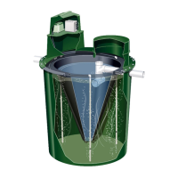
Description of the AP Series as an aerobic treatment facility.
How wastewater mixes with MLSS and air diffusion.
Process of solids settling and effluent leaving the plant.
How the OPS® operates and its components.
Meeting effluent quality standards and certifications.
Risks associated with raw sewage and microorganisms.
Proper respect and precautions when handling sewage.
Specific safety measures to follow.
Procedures for cleaning spills and leaks.
Potential hazards from treated effluent.
Seeking medical attention for sewage exposure.
Reporting accidents related to sewage exposure.
Explanation of the 50-11 Series OPS® for gravity applications.
Explanation of the 50-20 Series OPS® for on-demand applications.
Explanation of the 50-30 Series OPS® with 24 hr. timer.
Explanation of the 50-32 Series OPS® with micro-dose timer.
Approved compressor pump models for AP Series.
Effluent pump selection for standard and drip applications.
Technical details for the Grasslin 24 Hr. Timer.
Technical details for the Omeron Micro-Dose Timer.
Applications for the FM/1 series time switches.
Instructions for wiring the time switch unit.
Diagram showing terminal connections for the time switch.
Options for mounting the FM/1 series time switches.
How to program and use the manual override switch.
Operating the time switch in automatic mode.
Overriding programs using the manual switch.
Setting the current time and day of the week.
Programming the 7-Day and 24-Hour dials.
Use of FM/1 series timers in various equipment.
Technical specifications for FM/1 series timers.
Key features of the FM/1 series timers.
Table detailing available FM/1 series timer models.
Features of the H3CR-F DIN twin timers.
Explanation of the H3CR-F model number coding.
Table of H3CR-F models and their ordering information.
List of optional accessories for H3CR-F timers.
General and time range specifications for H3CR-F.
Electrical ratings for H3CR-F timers.
Detailed performance characteristics of H3CR-F.
Electromagnetic compatibility specifications for H3CR-F.
Graph showing the life expectancy based on load current.
Wiring connections for the H3CR-F timer.
Block diagram showing internal H3CR-F components.
Description of inputs and control outputs.
Diagrams for H3CR-F terminal arrangements.
Operating modes and functions of the timer.
Timing charts for Flicker OFF and Flicker ON start modes.
Explanation of the timer's parts and controls.
Overall dimensions of H3CR-F timers.
Dimensions with front connecting sockets.
Dimensions with back connecting sockets.
Warning about non-explosion proof lithium batteries.
Caution about explosion-proof lithium batteries.
General precautions for safe use of timers.
Environmental considerations for timer operation and storage.
Precautions related to power supply and voltage.
List of timer models applicable to specific precautions.
Countermeasures for AC 2-wire proximity sensors.
Handling input signals to prevent malfunction due to noise.
Precautions for using timers with relays.
Precautions for timers with non-contact outputs.
Additional safety precautions for timer usage.
OMRON's warranty terms and conditions.
Limitations on OMRON's liability for product use.
Considerations for product suitability in customer applications.
OMRON's responsibility for product conformity to standards.
Disclaimers regarding specifications, errors, and performance data.
Information on potential changes to product specifications.
Nominal dimensions and weights.
Disclaimer regarding catalog accuracy.
Use of performance data as a guide.
OMRON's non-responsibility for user programming.
Terms for catalog copying and reproduction.
Electrical schematics for SPI panels from '08 onwards.
Electrical schematic for Model 11.
Electrical schematic for Model 20.
Electrical schematic for Model 30.
Electrical schematic for Model 32.
Drawing for AP 500 ATU.
Drawing for LPA 500 ATU.
Drawing for AP 600 ATU.
Drawing for AP 750 ATU.
Drawing for AP 1000 ATU.
Drawing for AP 1500 ATU.
Guidelines for proper system operation and usage.
Template for an initial service contract.
Procedure for service technicians during site visits.
Checklist for service technicians to follow.
Checklist for proper system installation.
Details of the product's limited warranty.
Form for registering the product warranty.
Instructions on using the Sludge Judge tool.
Steps for converting between compressor types.
Information on locating compressor serial numbers.
Recommended practices for system maintenance and operation.
Prohibited actions and items to avoid flushing.
Duration of the limited warranty coverage.
Procedure for submitting a warranty claim.
Exclusions from the limited warranty coverage.
Governing laws and available legal remedies.
Suggested sludge levels for different tanks.
Steps for removing the existing compressor.
Steps for installing a new compressor.
Locations of serial numbers on AP Unit and OPS data plates.
| Brand | Hydro Action |
|---|---|
| Model | AP-500 |
| Category | Water Filtration Systems |
| Language | English |