2 Smartec HSA
INTRODUCTION
The purpose of this manual is to provide in-
formation useful in servicing the SMARTEC
®
HSA (high speed actuated) drive control drive
system. This manual includes the SMARTEC
®
general descriptions, electrical components,
servicing and troubleshooting procedures for
the drive control system.
Other than recommended hydrostatic main-
tenance identifi ed in the pump or transaxle
service manual, the (HSA) High Sped Actua-
tor does not require servicing during the life of
the vehicle in which it is installed. Should other
servicing be required, the exterior of the ma-
chine will need to be thoroughly cleaned be-
fore beginning most procedures. Do not use
a pressure washer to clean the hydrostatic
or system components.
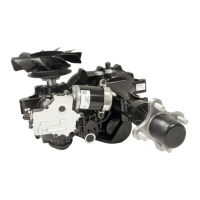
General Description
The SMARTEC
®
HSA Drive Control System
consists of two High Speed Actuators (HSAs)
mounted on either hydrostatic transaxles
or hydrostatic pumps; two Lap Bar Sensor
Modules (LBSMs) with required positioning
magnets; a Vehicle Integration Module (VIM),
and a Dynamic Stability Assist module (DSA).
The drive system performance and operation
is highly confi gurable. The SMARTEC
®
HSA
Drive Control System includes all compo-
nents required for an operator to control the
drive path of a vehicle excluding the vehicle
wire harness, and the vehicle operator in-
terface switches (e.g. seat switch, ignition
switch, brake switch, neutral switches, PTO
switch).
DESCRIPTION AND OPERATION