Options see section
4
- = standard 24 VDC power supply
12 = 12 V
DC power supply
A = max current limitation for ex-proof valves
P = electrical supply for external potentio-
meters to generate reference signal
W = power limitation function (see 6.7)
Digital electronic drivers type E-BM-AS
DIN-rail panel format, for proportional valves without transducer
Table G030-4/E
E-BM-AS digital drivers supply and con-
trol the current to the solenoid of Atos pro-
portional valves without transducer,
according to the electronic reference
input signal. The solenoid proportionally
transforms the current into a force, acting
on the valve spool or poppet, against a
reacting spring, thus providing the
hydraulic regulation.
E-BM-AS can drive up to two single or
one double solenoid proportional valves.
Electrical Features:
• 4 fast plug-in connectors
• RJ45 connector for RS232 Serial
communication to program the driver
with the Atos PC software
• 4 leds for diagnostics : power sup-
ply presence, driver status, solenoid
status (S1 and S2)
• ±5
VDC output supply for external refe-
rence potentiometers (/P option)
• Electrical protection against reverse
polarity of power supply
• Plastic box with IP20 protection degree
and standard DIN-rail mounting
• CE mark according to EMC directive
Software Features:
• Setting of valve’s functional parame-
ters: bias, scale, ramps, dither
• Linearization function for the hydraulic
regulation
• 2 selectable modes for electronic refe-
rence signal: external analog input or
internal generation
• Max power limitation (/W option)
• Selectable range of electronic referen-
ce analog inputs: voltage or current
• Complete diagnostics of driver status,
solenoid and driver fault conditions
• Intuitive graphic interface
E - BM -A 01H / **
Electronic driver in DIN
rail panel format
1 MODEL CODE
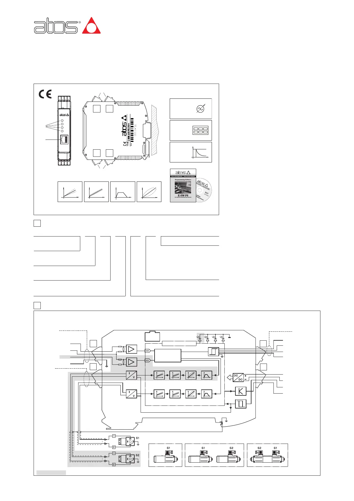
2 BLOCK DIAGRAM
Series number
G030
www.atos.com
01H = for single solenoid proportional valve
05H = for double solenoid or two single solenoid
proportional valves
C D
B A
POWER
STATUS
S1
S2
E-BM-AS
A = driver for valves without
transducer
PS -
S = digital execution
-
PS = Serial communication interface
RS232
CONNECTOR
CMD1
DGND
CMD2
REFERENCE
GENERATOR
LOGIC
CMD-
ENABLE input
STATUS output
DC/DC
CONVERTER
POWER
SUPPLY V+
POWER GND
MICROCONTROLLER
DRIVER STATUS
CURRENT TO
SOLENOID S1
CURRENT TO
SOLENOID S2
EARTH
REFERENCE S1
E-SW-PS
programming software
DI1
DI2
DI3
DI4
RAMPSLINEARIZ.
BIAS
SCALE
TWO SINGLE SOLENOID VALVES DOUBLE SOLENOID VALVE
POWER SUPPLY
SOLENOID S2
Only for 05H version
VALVE’S ELECTRICAL CONNECTORS
RAMPSLINEARIZ.BIASSCALE
D
C
A
B
RampsBiasScale
SOLENOID S1
REFERENCE S2
1
2
3
4
1
2
3
4
1
2
3
4
2
1
4
3
Linearization
Internal
Rererence
Generator
SINGLE SOLENOID VALVE
05H 05H01H
Electronic
reference
input signals
Current
supply to
solenoids
ON/OFF
inputs
Enhanced
Diagnostic
Hydraulic
Power
Limitation
(option /W)
RJ45
LEDS:
*S