Z-ME-KZ
DWN
ENT
I1
I2
I3
I4
I5
I6
I7
I8
A1
A2
O1
O2
O3
O4
O5
O6
O7
A3
A4
A5
ESC
UP
OK
X1 X2
RS232
PROFIBUS
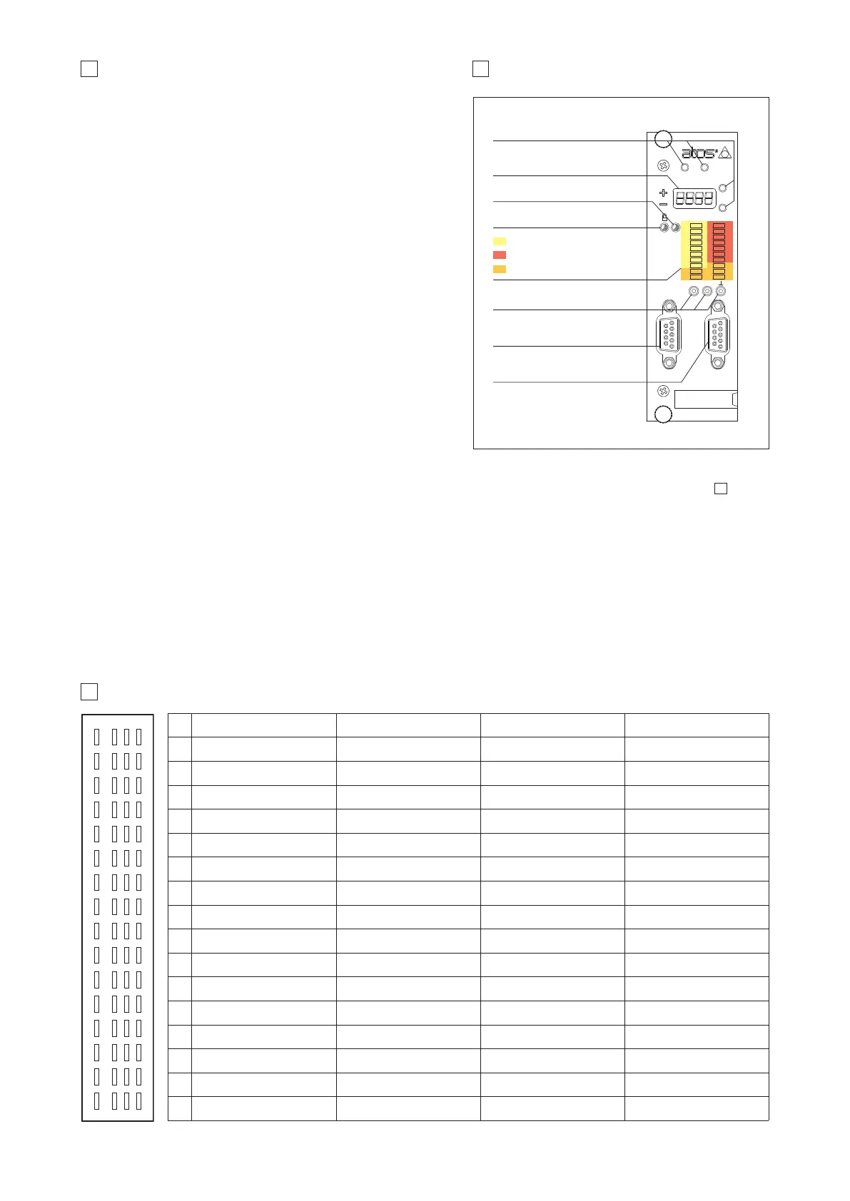
9 FRONT PANEL VIEW
Function Keys
Display
Active Led
OK Led
Digital Input Led
Digital Output Led
Auxiliary Led
Test Points
RS232 serial programming port
PROFIBUS-DP port (*)
(*) only for -BP option
8 FRONT PANEL DESCRIPTION
10 ELECTRONIC CONNECTIONS - 64 PIN REAR CONNECTOR
pin f d b z
2
DO 7 DI 1 F_TR2 + nc
4
SSI clock + DI 2 F_TR2 - nc
6
SSI clock - DI 3 F_INPUT + nc
8
SSI data + / Inc Ua1 DI 4 F_INPUT - nc
10
SSI data - / Inc /Ua1 DI 5 P_INPUT + nc
12
Inc Ua2 DI 6 P_INPUT - nc
14
Inc /Ua2 DI 7 F_TR1 + nc
16
Inc Ua0 DI 8 F_TR1 - nc
18
Inc /Ua0 ENABLE P_TR + nc
20
Inc +5VDC DO 1 P_TR - GND
22
nc FAULT VALVE_MONITOR + DO 3
24
nc nc VALVE_MONITOR - DO 4
26
nc DO 2 P_MONITOR + DO 5
28
CAN_GND nc AGND DO 6
30
CAN_L CONTROL_OUTPUT + VREF -10VDC V+
32
CAN_H F_MONITOR + VREF +10VDC V0
zbdf
2
4
6
8
10
12
14
16
18
(I) Input - (O) Output - (D) Digital transducers - (PS) Power supply - (F) Fieldbus interface, only for -BC option
20
22
24
26
28
30
32
rear view
(O)
(D)
(D)
(D)
(D)
(D)
(D)
(D)
(D)
(O)
(F)
(F)
(F)
(I)
(I)
(I)
(I)
(I)
(I)
(I)
(I)
(I)
(O)
(O)
(O)
(O)
(O)
(I)
(I)
(I)
(I)
(I)
(I)
(I)
(I)
(I)
(I)
(I)
(I)
(O)
(O)
(O)
(O)
(O)
(O)
(O)
(PS)
(PS)
G340
8.1 Keyboard and display
On the Z-ME-KZ front panel are available 4 function keys (ESC, ENT, UP, DWN),
and a numeric display (4 digits plus sign) to allow the user to view and change
the controller’s parameters as well as to display diagnostic messages.
The following parameters can be accessed (viewed or changed) via correspon-
ding menu structure:
- command and actual values
- analog input / output values
- digital input / output status
- position sensor indication
- force / pressure sensor indication
Parameter’s changes of the configuration, control gains, trigger conditions, inter-
nal cycle, fault monitoring are not allowed via front panel operations.
8.2 LED indication
The led indications are used to display the internal status (Active, OK) of the con-
troller or the status of the digital IO of the Z-ME-KZ. There are 22 led divided in
four different types:
- internal controller’s status (Active - OK)
- digital input status (I1 ÷ I8)
- digital output status (O1 ÷ O7)
- software programmable led (A1 ÷ A5) for specific functions
8.3 Test points
The test points present on the controller front panel can be used to monitor the
actual position (X1) and the force / pressure (X2) value measured by the relevant
transducers. Both signals are referred to the analog ground (
┴
) pin. The two
signals are respectively connected to P_MONITOR+ (X1) and F_MONITOR+ (X2)
analog output present on the rear connector of the controller card. These signals
can be software set to show other signals available in the controller (see 11.8 and 11.9).
8.4 Communication ports
On the front panel of the Z-ME-KZ is always present a serial RS232 port to program the controller by the Atos Z-SW software (see section ). All the
functional parameters of digital controller, like internal reference generation, controller dynamics, IO configurations, can be easily set and optimized by
the user.
For -BP or -BC options a second communication port dedicated to the selected fieldbus connection is present on the controller. For -BP option the
PROFIBUS-DP port is located on the front panel of the Z-ME-KZ controller. For -BC option the CANopen connection is located on the rear connector of the
Z-ME-KZ controller.
Through the fieldbus communication only the real-time parameters may be exchanged:
- position, velocity and force / pressure reference
- position, velocity and force / pressure feedback
- controller commands and status
- diagnostic / error messages
For more information about the front panel settings and fieldbus communication, please refer to the controller user manual.
12