C3 / +5 V
B1 / CMD1
C3 / +5 V
B1 / CMD1
B3 / CMD2
C3 / +5 V
B1 / CMD1
C4 / -5 V
10 KW
10 KW
10 KW
10 KW
B2 / CMD-
B2 / CMD-
1 single solenoid valve
5
SOFTWARE TOOLS
The driver configuration and parameters can be easily set with the Atos E-SW-PS programming software.
A serial RS232 connection is required between the PC and the electronic driver.
For a more detailed decription of software interface, PC requirements and cable/adapter characteristics please refer to technical tab. G500.
Programming software, must be ordered separately :
E-SW-PS (mandatory - first supply) = Dvd including E-SW-PS software installer and operator manuals; it allows the registration to Atos digital service
E-SW-PS-N (optional - next supplies) = as above but not allowing the registration to Atos digital service
On first supply of the E-SW-PS software, it is required to apply for the registration in the Atos download area : www.download.atos.com .
Once the registration is completed, the password will be sent by email.
The software remains active for 10 days from the installation date and then it stops until the user inputs his password.
With the password you can also download, in your personal area, the latest releases of the Atos software, manuals, drivers and configuration files.
Cable and adapter, can be ordered separately :
E-C-PS-DB9/RJ45 = cross cable from DB9 connector (PC communication port) to RJ45 connector (driver communication port)
E-A-PS-USB/DB9 = adapter from DB9 to USB connector (PC communication port); required if the DB9 communication port is not available on the PC
4.1 Power supply and wirings
The power supply must be appropriately stabilized or rectified and filtered: apply at least a 10000 mF/40 V capacitance to single phase rectifiers or a
4700 mF/40 V capacitance to three phase rectifiers.
A safety fuse is required in series to each driver power supply: 2,5 A fuse for 01H version and 5 A fuse for 05H version.
Option /12: This driver execution is designed to receive a 12 V
DC power supply and it is commonly used in mobile application.
A safety fuse is required in series to each driver power supply: 4 A fuse for 01H version and 6,3 A fuse for 05H version
4.2 Reference Input Signals (pin B1 and B3, both referred to pin B2)
The driver proportionally transforms the external reference input signal into the current supplied to the solenoid.
The driver is designed to receive one (01H) or two (05H) analog reference inputs (CMD1 on pin B1, CMD2 on pin B3); both signals are referred to a
common electric ground (CMD- on pin B2).
The input range is software selectable among voltage (0 ÷ ±10 V
DC) or current (4 ÷ 20 mA with cable break detection or 0 ÷ ±20 mA).
Default settings: 0 ÷ 10 V
DC for two position valves; 0 ÷ ±10 VDC for three position valves (see valve’s tech. table). Other ranges can be set by
software. Internal reference generation is software selectable (see 6.6).
Note: software selection of analog input range (voltage or current) is applied to both signals CMD1 and CMD2.
4.3 Pressure Input Signal (pin B3 referred to pin B2, /W option)
When hydraulic power limitation is active (see 6.7), input signal CMD2 must be connected to an external pressure transducer installed on the
hydraulic system; maximum input range 0 ÷ 10 V
DC.
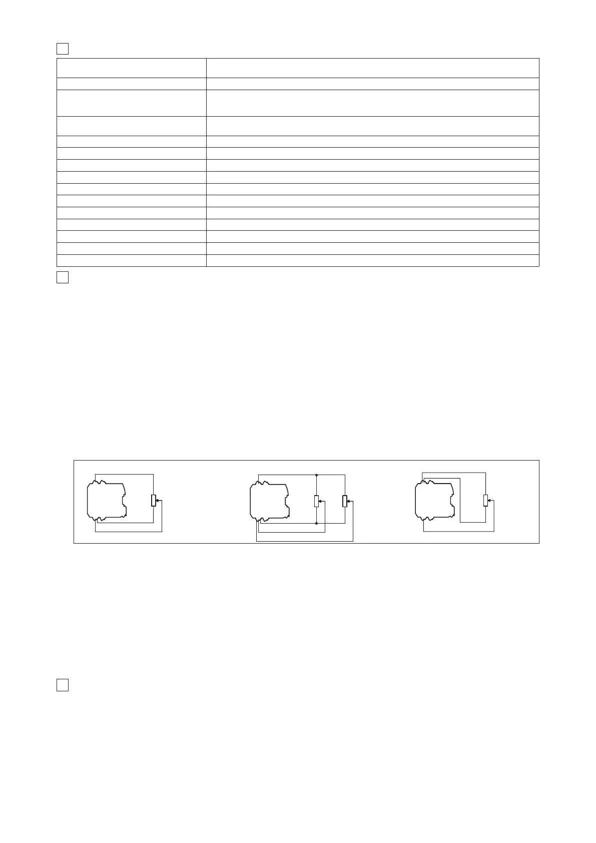
4.4 Output supply Signal for external reference potentiometers (/P option)
The reference analog signals can be generated by one (01H) or two (05H) external potentiometers directly connected to the driver, using the ±5 V
DC
supply output available at pin C3 and C4.
4.5 Enable Input Signal (pin D3 referred to pin D2)
Enable input signal allows to enable/disable the current supply to the solenoids, without removing the electrical power supply to the driver; it is used
to maintain active the serial connection and the other driver functions when the valve must be disabled for safety reasons.
To enable the driver, supply a 24V
DC on pin D3 referred to pin D2.
4.6 Status Output Signal (pin D4 referred to pin D2)
Status output signal indicates fault conditions of the driver (short circuits, solenoids not connected, cable broken for 4 ÷ 20mA input)
and is not affected by Enable input signal status: fault presence corresponds to 0 V
DC, normal working corresponds to 24 VDC.
When hydraulic power limitation function is active (see 6.7), status output signal can be software configured to indicate power limitation status:
not active (0 V
DC) or active (24 VDC).
4.7 ON/OFF Input Signals (pin C1...C4 referred to DGND pin B4 )
When the driver is configured in internal reference generation mode (see 6.6), the 4 ON/OFF input signals (DI) are used to select the active referen-
ce signal, among the available stored values. If the 4 ON/OFF input signals (DI) are not active, the driver can be commanded by external analog
reference. The polarity of the digital inputs can be customized: active status = 24 V
DC is the default setting.
Note: with /P option two ON/OFF signals are available as digital inputs (DI).
4.8 Possible combined options: /12W, /12PW, /AW, /PW and /APW (only for 05H); /12P and /AP (for 01H and 05H).
4 SIGNALS SPECIFICATIONS
3 MAIN CHARACTERISTICS OF E-BM-AS ELECTRONIC DRIVERS
Power supply (see 4.1)
Standard Nominal: +24 VDC Rectified and filtered: VRMS = 20 ÷ 32 VMAX (ripple max 10 % VPP)
option /12 Nominal: +12 V
DC Rectified and filtered: VRMS = 10 ÷ 14 VMAX (ripple max 10 % VPP)
Max power consumption 50 W for 01H version; 100 W for 05H version
Current supplied to solenoids
IMAX = 2.7 A with +24 VDC power supply to drive standard proportional valves (3,2 W solenoid)
I
MAX = 3.3 A with +12 VDC power supply to drive proportional valves with /6 option (2,1 W solenoid)
I
MAX = 2.5 A with +24 VDC power supply to drive ex-proof proportional valves (3,2 W solenoid) for /A option
Reference input signal (see 4.2)
Voltage: range ±10 VDC Input impedance: Ri > 50 kW
Current: range ±20 mA Input impedance: Ri = 500 W
Enable and ON/OFF inputs (see 4.5, 4.7)
Range : 0 ÷ 24 VDC ( OFF state: 0 ÷ 5 VDC ; ON state: 9 ÷ 24 VDC ) Input impedance: Ri > 10 kW ;
Output supply (see 4.4)
±5 VDC @ max 10 mA : output supply for external potentiometers (only for /P option)
Status output (see 4.6) Output range : 0 ÷ 24 VDC ( ON state > [power supply - 2 V] ; OFF state < 1 V ) @ max 1,4 A
Alarms Solenoid not connected, short circuit and cable break with current reference signal
Format Plastic box ; IP20 protection degree ; L 35 - H 7,5 mm rail mounting as per EN60715
Operating temperature -20 ÷ 60 °C (-20 ÷ 40 °C on 05H version for two single solenoid proportional valves; storage -25 ÷ 85 °C)
Mass 130 g
Additional characteristics Short circuit protection of current output to solenoids; protection against reverse polarity of power supply
Electromagnetic compatibility (EMC) According to Directive 2004/108/CE - Immunity: EN 61000-6-2 (2005); Emission: EN 61000-6-4 (2001)
Communication interface
RS232 serial connection (not insulated), Atos protocol with ASCII coding (see section
5
)
Recommended wiring cable LiYCY shielded cables: 0,5 mm
2
for length up to 40 m [1,5 mm
2
for power supply and solenoids]
2 single solenoid valves
1 double solenoid valve
01H 05H
05H