3 POSITION REFERENCE MODE
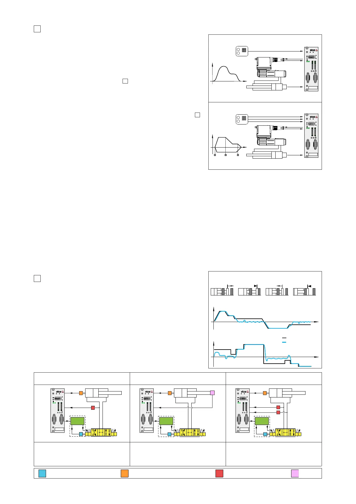
3.1 External reference generation
Z-ME-KZ controller regulates in closed loop the actuator position according to an external
reference position signal and to the position feedback from the actuator transducer. It
generates a reference signal for the proportional valve which regulates the hydraulic flow
to the actuator.
The external reference signal can be software selected among:
Analog reference (a)
The controller receives in real time the reference signal from the machine electronic central
unit by means of the analog input (see section ) limiting speed, acceleration and dece-
leration values.
Fieldbus reference (b)
The controller receives in real time the reference signal from the machine electronic central
unit by means of the digital fieldbus communication (-BC and -BP executions) limiting
speed, acceleration and deceleration values.
For fieldbus communication details, please refer to the controller user manual (see section ).
3.2 Internal reference generation
Z-ME-KZ controller regulates in closed loop the actuator position according to an internally
generated reference position signal and to the position feedback from the actuator tran-
sducer. It generates a reference signal for the proportional valve which regulates the
hydraulic flow to the actuator.
The internal reference signal is generated by a pre-programmed cycle; only start, stop and
switch-over commands are required from the machine electronic central unit by means of:
- on-off commands (c)
- fieldbus commands (d)
12
10
4
POSITION / PRESSURE OR FORCE CONTROL
Alternated pressure or force control can be added to the actuator’s standard position con-
trol (see below functional schemes).
Remote transducers (pressure or force) have to be installed on the actuator.
The position/pressure (or position/force) controls are operated according to two separate
reference signals and a dedicated algorithm automatically selects which control is active
time by time.
The dynamics of the switching between the two controls can be regulated thanks to speci-
fic software setting, in order to avoid instability and vibrations.
Position control is active (see phase and at side) when the actuator actual pressure
or force is lower than the relevant reference signal.
Pressure or force control is active (see phase and at side) when the actuator actual
pressure or force, measured by remote transducers, grows up to the relevant reference
signal - the controller reduces the valve’s regulation in order to limit the actuator pressure
or force; if the pressure or force tends to decrease under its reference signal, the position
control returns active.
Alternated Position/Pressure Control Alternated Position/Force Control - Load cell
Alternated Position/Force Control - Two pres-
sure transducers
DRIVER
P
T
AB
PT
M
Z-ME-KZ
O1
O2
O3
O4
O5
O6
O7
A3
A4
A5
I1
I2
I3
I4
I5
I6
I7
I8
A1
A2
X1 X2
OK
DWN
UP
ENT
ESC
RS232
PROFIBUS
DRIVER
T
AB
PT
M
L
Z-ME-KZ
O1
O2
O3
O4
O5
O6
O7
A3
A4
A5
I1
I2
I3
I4
I5
I6
I7
I8
A1
A2
X1 X2
OK
DWN
UP
ENT
ESC
RS232
PROFIBUS
DRIVER
T
AB
PT
M
P
P
Z-ME-KZ
O1
O2
O3
O4
O5
O6
O7
A3
A4
A5
I1
I2
I3
I4
I5
I6
I7
I8
A1
A2
X1 X2
OK
DWN
UP
ENT
ESC
RS232
PROFIBUS
one remote pressure transducer has to be
installed on the actuator’s port to be controlled
one load cell transducer has to be installed
between the actuator and the controlled load
two remote pressure transducers have to be
installed on the actuator’s ports; the actuator
force is calculated by the pressure feedbacks
(Pa - Pb)
valve’s spool transducer actuator’s position transducer pressure transducer load cell
M
Z-ME-KZ
O1
O2
O3
O4
O5
O6
O7
A3
A4
A5
I1
I2
I3
I4
I5
I6
I7
I8
A1
A2
ESC
ENT
UP
DWN
OK
X1 X2
RS232
PROFIBUS
M
Z-ME-KZ
O1
O2
O3
O4
O5
O6
O7
A3
A4
A5
I1
I2
I3
I4
I5
I6
I7
I8
A1
A2
ESC
ENT
UP
DWN
OK
X1 X2
RS232
PROFIBUS
t
t
External reference generation
Internal reference generation
force
forward
movement
backward
movement
force
control
force
control
reference value
actual value
Atos PC software allows to design a customized sequence of motion phases adapted to the specific application requirements: a range of predefined
standard sequences are available in the Z-SW software.
Start/stop/switch-over commands and reference generation type can be set for each phase in order to realize an automatic cycle according to the appli-
cation requests. Refer to the controller user manual for further details on the available selection of start/stop/switch-over commands and reference gene-
ration type.
Start/stop/switch-over commands examples
External digital input on-off commands, on rear connector, are used to start/stop the cycle generation or to change the motion phase
External fieldbus input on-off commands, by fieldbus communication, are used to start/stop the cycle generation or to change the motion phase
Switch by position switch-over from actual to following motion phase occurs when the actual position reaches a programmed value
Switch by time switch-over from actual to following motion phase occurs after a fixed time, starting from the actual phase activation
Switch by internal status switch-over from internal status are used to start/stop the cycle generation or to change the motion phase
Internal reference generation types examples
Absolute a target position reference signal is internally generated for each motion phase; maximum speed, acceleration and
deceleration can be set to obtain a smooth and precise position control
Relative as ‘Absolute’ but the target position corresponds to the actuator position plus a fixed quote internally set by software
Hold the controller holds the actual position
Machine
central unit
Machine
central unit
Analog
(a) or Fieldbus (b)
reference
Valve command
and monitor
position
t
Valve command
and monitor
On-off
(c) or Fieldbus (d)
commands
pos
Speed profile generated
switch-over points
Speed profile generated