10
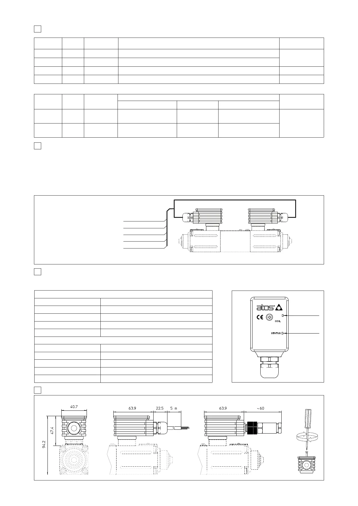
DIMENSIONS [mm] AND INSTALLATION
/M12 option
10/13
COIL (YELLOW LED)
Light signal displayed Coil status
Light Off PWM command OFF
Light On PWM command ON
Slow blinking Solenoid not connected
Fast blinking Short circuit on the solenoid
STATUS (GREEN LED)
Light signal displayed Driver status
Light Off Absence of power supply
Light On Malfunctioning
Slow blinking Driver disabled or Alarm present
Fast blinking Driver enabled
COIL LED
(yellow)
STATUS LED
(green)
It is possible to verify the actual status of solenoid command (yellow LED) and the driver status (green LED).
The following table details the possible displayed conditions:
Standard cable
wire color
/M12 option
pin
SIGNAL TECHNICAL SPECIFICATIONS NOTES
RED 1 V+ Power supply +24 VDC or +12 VDC (see 4.1)
Input - power supply
BLACK 2 V0 Power supply 0 VDC
WHITE 3 AGND (Signal zero) Ground for CMD1,CMD2 and OUTPUT SUPPLY Input - analog signal
GREEN N.A. OUTPUT SUPPLY +5 VDC @ 5 mA output supply for external potentiometer (not available for option /M12) (see 4.4) Output - analog signal
7 DRIVER CONNECTIONS
9
DIAGNOSTIC LEDS
It is possible to use two E-MI-AS drivers to operate one double solenoid proportional valve supplying the same analog signal to both CMD1 inputs referen-
ce. The enable input signal is used to select which driver/solenoid has to be active.
To operate double solenoid valves it is required to:
- parallel wire the two drivers (see following scheme).
- select opposite polarity (default and reverse) for the two enable signals (see 4.5)
- manage from PLC or machine unit: 1 analog reference signal corresponding to desired valve’s regulation and 1 ON/OFF signal to select the active
solenoid.
8 DOUBLE SOLENOID VALVES OPERATION
Numbers inside brackets are referred to 5 poles connector (option /M12)
SOLENOID S2 SOLENOID S1
CMD 1 : reference input signal 0 ÷ +10 V
DC
CMD 2 : S1/S2 solenoid enable 0 or +24 VDC
AGND : signal zero
V+ : power supply +24 V
DC
V0 : power supply 0 VDC
YELLOW (PIN 4)
BLUE (PIN 5)
WHITE (PIN 3)
RED (PIN 1)
BLACK (PIN 2)
Standard cable
wire color
/M12 option
pin
SIGNAL
TECHNICAL SPECIFICATIONS (software setting dependent)
NOTES
Default
(see 4.2 ; 4.5)
Internal Reference
Generation (see 4.6 ; 6.6)
Hyraulic Power Limitation
(only for /W option - see 4.3 ; 6.7)
YELLOW 4 CMD 1
Reference analog input: 0 ÷ 10 VDC
(4 ÷ 20 mA; 0 ÷ 20 mA for /I option)
ON/OFF: 24 VDC / 0 VDC
Reference analog input: 0 ÷ 10 VDC
(4 ÷ 20 mA; 0 ÷ 20 mA for option /I)
Input - analog or digital
BLUE 5 CMD 2 Enable/disable the driver: 24VDC / 0VDC ON/OFF: 24 VDC / 0 VDC Pressure transducer input: 0 ÷ 10 VDC
Standard version
The two input signals CMD1 and CMD2 can be managed as analog input or ON/OFF signals; their function depends on the selected software setting:
max torque
50 cNm
ZH-5P