Power supply
(positive at contacts 2a, 2c)
(negative at contacts 4a, 4c)
Max power consumption 50 W
Current supplied to solenoid Imax= 3.3A square wave PWM type; (for ex-proof valves Imax = 2,5 A)
Nominal reference signal, factory preset E-ME-AC-01F: 0
÷+5V at contact 12c (GND on 8a)
E-ME-AC-05F: ± 5V at contact 12c (GND on 8a)
4 ÷20 mA for /I: at contacts 12c (+) and 8a (-)
Reference signal variation range (Scale adjust) ± 10V max ± 2,5V min
Input signal impendence Voltage signal Ri > 50 KOhm - (/I option Ri = 316 Ohm)
Potentiometers supply +5V / 50 mA at contact 10c and -5V / 20mA at contact 14c
Ramp time 5 sec. max (0 ÷100% of reference signal)
Enabling signal V = 5 ÷24V
DC
on contact 18a with led indicator on panel
Electrical wiring Coil : 2 x 1 mm
2
to 20 m 2 x 1,5 mm
2
shielded to 40 mt
Card format Europe 100x160 mm (Plug-in unit DIN 41494)
Card connector Male DIN 41612 /D
Connector elements available Type E-K-32M frame snap connector (see table G800) To be ordered separately
Operating temperature 0 ÷50°C (storage -20° ÷+70°C)
Front panel dimensions 128,4 x 35,3 mm
Weight 540 g
Features Rapid solenoid excitation and switching off.
Outputs to solenoids protected against accidental short circuits
3 MAIN CHARACTERISTICS OF E-ME-AC ELECTRONIC DRIVERS
4 GENERAL SPECIFICATIONS
4.1 Power supply and wirings
The power supply must be appropriately stabilized or rectified and filtered. If the power supply is
generated by a single phase rectifier, use a 10000 µF/40V capacitor; if pulse voltage is generated
by a three phase rectifier, connect a 4700 µF/40V capacitor (see ).
Connect the reference signal to the main electronic control by means of shielded and twisted
cables. Pay attention: the negative and the positive poles must not be exchanged each other.
Shield the wirings to avoid electromagnetic noise (EMC).
It is suitable to keep the driver and its cables far from any electromagnetic radiation source (like
cables where high currents flow, electric motors, transformers, relays, solenoids, portable radio-
transmitter, etc.).
Wire the earth connection as shown in , according to CEI EN 60204-1 standards.
Connect the shield of the driver to the noiseless earth terminal (TE) .
4.2 Reference signal
The electronic driver is designed to receive voltage or current reference signals according to the
following options:
– internal potentiometers mounted on board, see
.
– external reference signals, see
Note that drivers designed to receive current reference (options /I) have signal values in the range
4 to 20 mA and do not have mounted on board potentiometer option.
It is possible to use current option also for double channels drivers type E-ME-AC-05F using the
reference inversion signal on contact 18c (5 ÷ 24 V
DC
).
4.3 Monitor signal
This voltage output signal allows to measure the current supplied to the coil, read by a voltmeter
on the front panel test points (see ). Reading scale is 1 mV = 1 mA.
To visualize the signals use voltmeters with impedance >10 K
Ω
.
4.4 Set code
Basic calibration of the electronic driver is factory preset according to the proportional valve it has
to be coupled with. These pre-calibrations are identified by a standard number in the model code
as follows:
1 = RZGO, KZGO 2 = RZMO,AG*ZO, LI*ZO
3 = DHZO, DKZOR 4 = DPZO-A-*5, DPZO-A-*7
6 = QV*ZO(R), LIQZO
For ex-proof valves, insert an “A” before the code of adjustment.
For example, the code of adjustment for RZGA is A1 (see table E120).
4.5 Calibrations/settings available to the user, see
, , ,
,
.
Scale
The Scale regulation, available on the front panel, permits to modify the relation between the refe-
rence signal and the regulated current to the solenoid.
Modifying this regulation (see , ) it is possible to fit the valve hydraulic behaviour to the effecti-
ve system conditions; in addition, the two regulations available for double solenoid valves (driver
E-ME-AC-05F) permit to set different hydraulic adjustments for positive and negative movements.
The Scale regulation is factory set at standard values depending to the proportional valve to be
controlled and it is identified by the driver set code (see 4.4)
Bias
The bias regulations, available on the front panel, permit to set the correspondence between the
electrical zero of the reference signal with the beginning of the valve’s hydraulic regulation, com-
pensating the dead band and the component’s mechanical tolerances .
Modifying this regulation (see , ) it is possible to fit the valve hydraulic behaviour to the effecti-
ve system conditions; in case of drivers for double solenoid valves (E-ME-AC-05F) the bias are
active only when the reference signal is over the threshold value of ± 100 mV.
The Scale regulation is factory set at the standard values depending to the proportional valve to be
controlled and it is identified by the driver set code (see 4.4)
Ramps
The ramp regulation, available on the front panel, permit to modify the time in which the regulated
current reaches the set value in front of a step change of the reference signal.
The ramp regulation is factory set at value close to zero and it can be increased up to 5 sec max
for a step change of the reference signal from 0% to 100%
1110
9
1110
15
11
13
5
10986
13
13
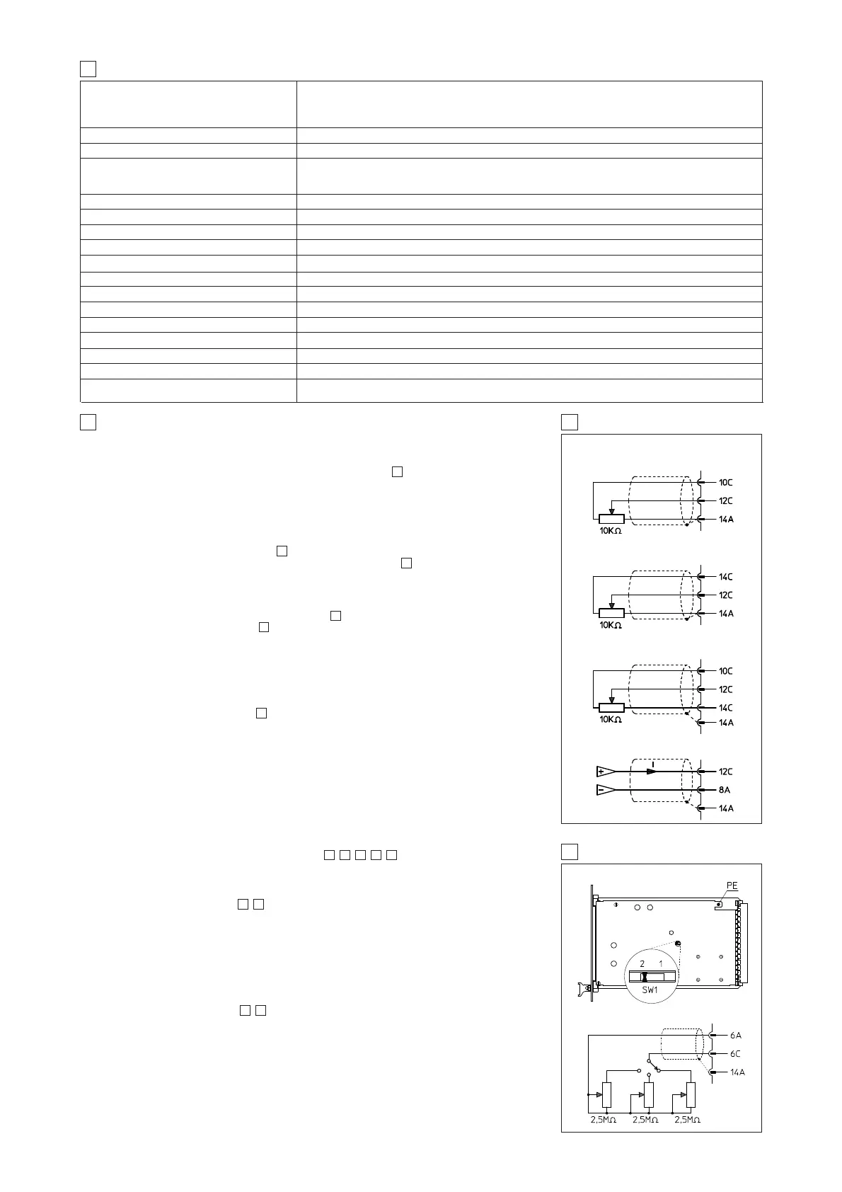
5 EXTERNAL REFERENCE SIGNALS
Nominal: :24V
DC
Rectified & filtered: :V
RMS
= 21 ÷ 33 (max ripple = 2Vpp)
EXTERNAL
POTENTIOMETER
CONNECTIONS
SOLENOID S1 REFERENCE
SOLENOID S2 REFERENCE
SOLENOIDS S1 AND S2 REFERENCE
EXTERNAL REFERENCE GENERATOR
AND /I OPTION
6 EXTERNAL RAMPS
EXTERNAL RAMP SELECTION
EXAMPLE WITH THREE EXTERNAL RAMPS