G035
The available ramp regulations depend to the driver version:
- in the standard version it is available a single regulation for rise/fall ramp (P7)
- in the /RR version it is possible to separately regulate the rise ramp and the fall ramp (P7 and
P17)
In the version /4R-4 it is possible to separately regulate the ramp for each of the internal reference
signals (P11-P12-P13-P14).
External ramps, see
This feature allows to regulate the ramp time by means of external potentiometers. In order to use
this capability:
- set switch SW1 in position 2
- connect one or more external potentiometers as shown (use only 2,5 MΩ potentiometers).
Internal reference signals
In the version -4, /RR-4 and /4R-4 the driver can self generate 4 different internal reference signals,
selectable by means of 4 relevant on-off commands 24 V
DC, to be supplied to the contacts 22c,
24c, 24a, 22a (see scheme
,
): each internal reference signal can be adjusted by means of a
relevant potentiometer available on the front panel.
6
1413
7 INSTALLATION AND START-UP
It is advisable to perform calibration procedures in the order given below.
7.1 Warning
– Never insert or remove the driver while the electronic system is powered on.
– Voltages must always be measured with reference to GND (connector contact 8a or front panel
test point ).
– Refer to to identify components mentioned in calibration procedures.
7.2 Start-up
Factory pre-set adjustments might not meet the desired requirements for the specific application
and performances can be optimized by on-site re-adjustements of Bias, scale and ramps potentio-
meters, in sequence.
– Connect the electronic driver according to the desired connection diagram,
,
.
The current supplied to the coil can be measured by a voltmeter connected between the test
points on the front panel.
For E-ME-AC-05F the channel enabled led (L5 or L6) shows the supplied coil.
Enabling signal, see ,
.
The electronic driver operate when the contact 18a is supplied with an enabling signal (usually
24V
DC
). It could be useful in emergency conditions to inhibit the driver by zeroing this signal.
Bias adjustment (Dead band compensation), see
, , .
– Supply a reference signal voltage (0V
DC
for E-ME-AC-01F and ± 0,1V
DC
for E-ME-AC-05F).
Gradually turn bias potentiometer(s) until a movement of the controlled actuator is obtained
– Turn in the opposite direction until the actuator is stopped.
Scale adjustment, see
, , .
Supply max reference voltage signal (for E-ME-AC-05F driver repeat for max negative voltage) in
the specified range and turn scale potentiometer(s) until the actuator speed reaches the desired
value.
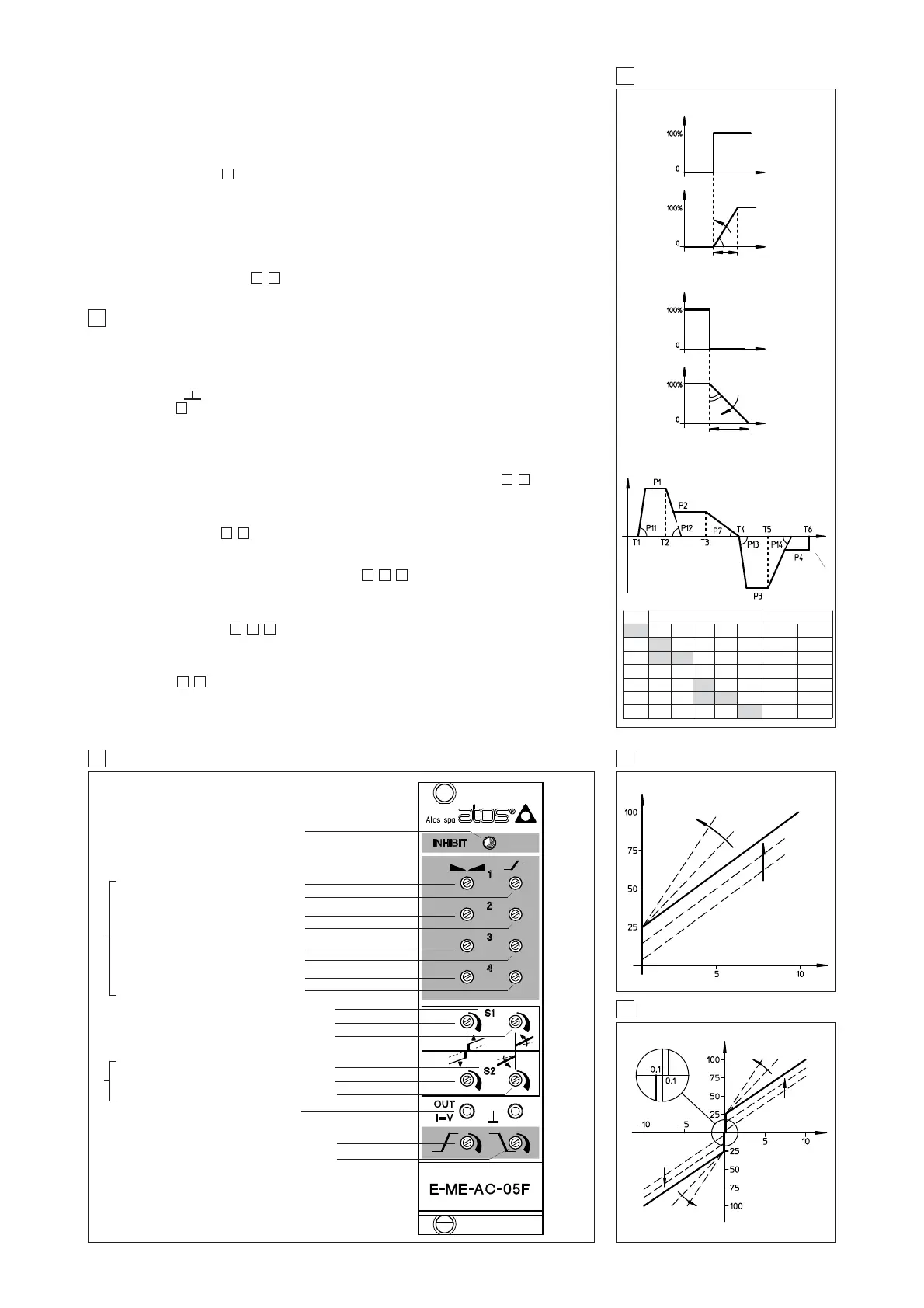
Ramps, see , .
Turning the ramp potentiometer(s) clockwise, acceleration(s) and deceleration(s) can be reduced
to obtain optimization of the complete system.
14
98
11109
11109
13
1413
9
9 E-ME-AC-05F TOPOGRAPHICAL VIEW OF REGULATIONS
8 RAMPS AND SETTINGS
10 E-ME-AC-01F ADJUSTMENT
11 E-ME-AC-05F ADJUSTMENT
Current [%]
Reference [V]
SCALE ADJUST
BIAS ADJUST
Reference
[V]
SCALE ADJUST
BIAS S1
ADJUST
Reference potentiometer P1
Ramp regulation P11
Reference potentiometer P2
Ramp regulation P12
Reference potentiometer P3
Ramp regulation P13
Reference potentiometer P4
Ramp regulation P14
Drive enabled led (solenoid S1) L5
Bias solenoid S1 P5
Scale adjust for solenoid S1 P15
Drive enabled led (solenoid S2) L6
Bias solenoid S2 P6
Scale adjust for solenoid S2 P16
Current monitor point (mV read = mA)
Acceleration and deceleration ramp P7
Decelaration ramp (option /RR only) P17
1) Reference pot. P1, P2, P3, P4 mounted in -4, /RR-4, /4R-4
options.
Ramps pot. P11, P12, P13, P14 mounted only in /4R-4
option.
2) Only for E-ME-AC-05F/*
1)
2)
BIAS S2
ADJUST
Current [%]
Card disabled led L7
INTERNAL RAMPS - /RR OPTION
/4R-4 OPTION
Reference from 0 to 100%
Reference
time
time
No ramp
time
time
time
rampa time
Adjust ramp time
with P7
ramp time
Reference from 100% to 0
Adjust ramp time
with P17
Time Selected inputs Active regulations
REF.1 REF.2 REF.3 REF.4 6a-6c Speed Ramp
T1 ON OFF OFF OFF Open P1 P11
T2 ON ON OFF OFF Open P2 P12
T3 OFF OFF OFF OFF Open EXT.REF. P7
T4 OFF OFF ON OFF Open P3 P13
T5 OFF OFF ON ON Open P4 P14
T6 OFF OFF OFF OFF Close EXT.REF. (tr=0)