G025
6 INSTALLATION AND START-UP
It is advisable to perform calibration procedures in the order given below.
6.1 Warning
– Never insert or remove the driver while the electronic system is powered on.
– Protect the regulator on power line with an external fuse (2,5A RTV for version E-BM-AC-01F
and E-BM-AC-05F; 5A RTV for E-BM-AC-011F)
– Refer to section to identify components mentioned in calibration procedures.
– It is possible to install the E-BM-AC driver on front panel (drilling plane 33,5x68,5 mm) or on
back panel DIN guide (see fig. ).
The electrical connection is made on the clamps of the proper UNDECAL type E-K-11B socket,
equipped with antivibrating spring.
6.2 Start-up
Factory pre-set adjustments might not meet the requirements desired for the specific application.
Performances can be optimized by on-site re-adjustments of Bias, Scale and ramps potentiome-
ters, in sequence.
– Connect the electronic driver according to the desired connection diagram, (see
, ,
).
– The current supplied to the coil can be measured by a voltmeter connected between the test
points on the front panel.
The reading range will be: l[mA] = V[mV].
Bias adjustment (dead band compensation), see
, , .
For E-BM-AC-01F and E-BM-AC-11F:
– supply a reference signal voltage R1 = +0,2 V
DC
;
– turn clockwise the potentiometer P1 for solenoid S1 until the movement of the controlled actua-
tor is obtained.
– turn the potentiometer P1 in the opposite direction until the actuator is stopped.
– for version E-BM-AC-011F repeat the operation and supply a reference signal voltage R2 =
+0,2 V
DC
by the potentiometer P2.
For E-BM-AC-05F:
– supply a reference voltage R1 = +0,2 V
DC
;
– turn clockwise the potentiometer P1 for solenoid S1 until the movement of the controlled actua-
tor is obtained.
– turn the potentiometer P1 in the opposite direction until the actuator is stopped.
– repeat the operation and supply a reference signal voltage R1 = -0,2 V
DC
by the potentiometer
P2.
Scale adjustment (see
, ,
)
Supply max. reference signal voltage R1 (for E-BM-AC-05F driver repeat for max. negative referen-
ce voltage signal R1) in the specified range and turn scale potentiometer P3 (P4 for negative refe-
rence signal) until the actuator speed reaches the desired value.
For version E-BM-AC-011F repeat the operation and supply the max positive reference signal R2
by the potentiometer P4.
Ramps, see
,
.
Turning the ramp potentiometer(s) clockwise, acceleration(s) and deceleration(s) can be reduced
to obtain the optimization of the complete system.
97
11109
11109
15145
8
9
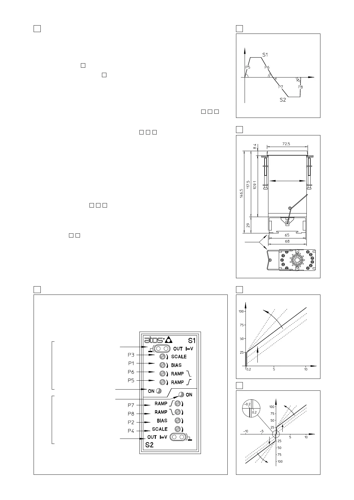
9 E-BM-AC-05F TOPOGRAPHICAL VIEW OF REGULATIONS
7 RAMPS
10 E-BM-AC-01F and 011F ADJUSTMENT
11 E-BM-AC-05F ADJUSTMENT
Current monitor test point
(mV read - mA)
Scale adjustment
Bias
Deceleration ramp (*)
Acceleration ramp
S1 channel enabled led
S2 channel enabled led
Acceleration ramp
Deceleration ramp (*)
Bias
Scale adjustment
Current monitor test point
(mV read - mA)
8 DIMENSIONS (mm)
UP AND DOWN
DISSYMETRICAL
RAMP GENERATOR
E-K-11B UNDECAL
SOCKET FOR
GUIDE DIN EN
50022-50035
MOUNTING
BOLTS FOR PANEL
FASTENING
[%] Current
BIAS ADJUSTMENT
P1, P2
SCALE ADJUSTMENT
P3, P4
Reference [V]
BIAS ADJUSTMENT
P1
[%] Current
SCALE
ADJUSTMENT P3
SCALE
ADJUSTMENT P4
Valve opening
Time
BIAS ADJUSTMENT
P2
S1
S2
S1, S2
E-K-11B
Reference [V]
SOLENOID S2 SOLENOID S1
(*) only for option /RR