P/N 42-9450 8/08 Copyright 2008 Hydrotherm
Page 37 KN INSTALLATION AND OPERATION INSTRUCTIONS
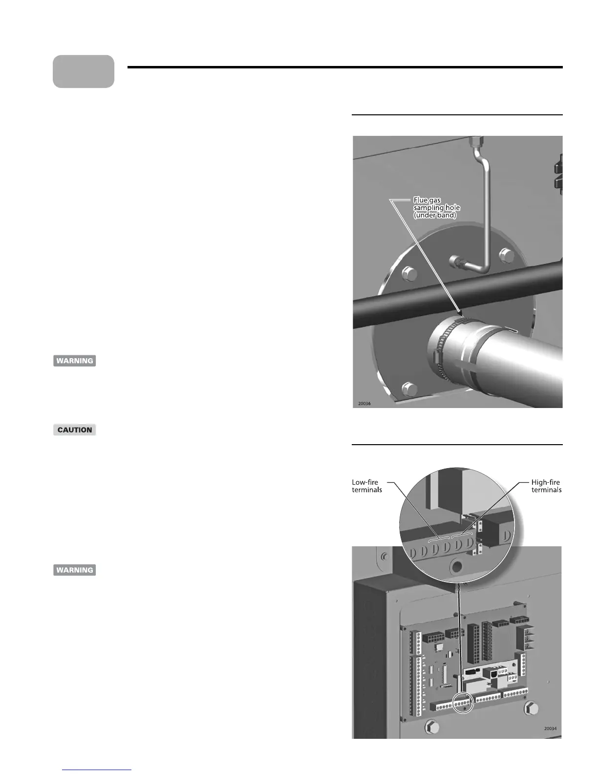
Figure 27 Flue gas sampling hole
Figure 28 Electrical panel
Starting the boiler (continued)
Turn the boiler OFF
Tu rn OFF the boiler on/o switch and allow the boiler to cycle o .
2. CLOSE the manual gas valve.
3. Multiple boiler HeatNet applications Disconnect the communications cable
or 3-wire connection to the boiler connection board. (Replace when done.)
Check ignition
With the manual gas valve CLOSED, start the boiler with the on/o switch.
Look into the ame window, le side of the boiler (Figure 29, page 38).
When ignition starts, the spark should jump between the electrodes, not to other
surfaces.
e spark should be strong and steady. If the spark is acceptable, turn the boiler
on/o switch
OFF. en proceed with the start-up adjustment procedure.
If the spark jumps to ground or is unsteady, turn the boiler OFF. See the
Maintenance section of this manual for the procedure to remove and inspect the
electrode assembly. Replace the electrode assembly if it is damaged or not within
speci cations.
Insert combustion analyzer probe
e boiler must be checked and adjusted using combustion test
instruments. Failure to accurately measure ue gas analysis and adjust
the boiler as needed could result in severe personal injury, death or
substantial property damage.
A er the boiler has cycled o , loosen the hose clamp covering the ue gas sampling
hole (Figure 27).
e ue gas vent pipe may be hot. Touching the pipe with unprotected
skin could result in a severe burns.
2. Slide the hose clamp o of the sample opening.
3. Insert the combustion analyzer probe into the sample opening.
4. If using an electronic analyzer, zero and calibrate it before proceeding.
5. If usi
ng a chemical analyzer, make sure that the uid is fresh and is at room temperature.
Have a monoxer
and test tubes available to test carbon monoxide levels.
Check high re operation
Remove the electrical panel cover on the right side of the boiler (see item 11,
page 3) as in Figure 28.
Electrical shock hazard e electrical box contains line-voltage
wiring and contacts. Use caution when working in the electrical box to
avoid contact with line-voltage elements. Turn o power to the boiler
panel if necessary.
2. Connect a jumper wire across the high- re terminals of the connector board
(Figure 28). ese terminals are located on the lower row as shown.
3. Turn the boiler on/o switch ON.
4. e boiler will start at about 30% of maximum input and immediately go to high
r e .
5. Observe the ame through the ame window (le side of boiler; see Figure 29).
e ame should be blue and well-de ned, with white traces.
If the ame is too lean (too much air), it will be light blue and unsteady.
If the ame appears reddish, or there are red areas on the burner surface, turn
the boiler
OFF and reduce fuel with the gas valve thro le (see page 38).
6. Check the analyzer. A rapid increase in CO is an indicator of bad combustion.
Turn the boiler OFF and reduce fuel input as explained on page 38.
1.
1.
2.
3.
4.
5.
1.
1.
•
•
•
12
 Loading...