P/N 42-9450 8/08 Copyright 2008 Hydrotherm
Page 38 KN INSTALLATION AND OPERATION INSTRUCTIONS
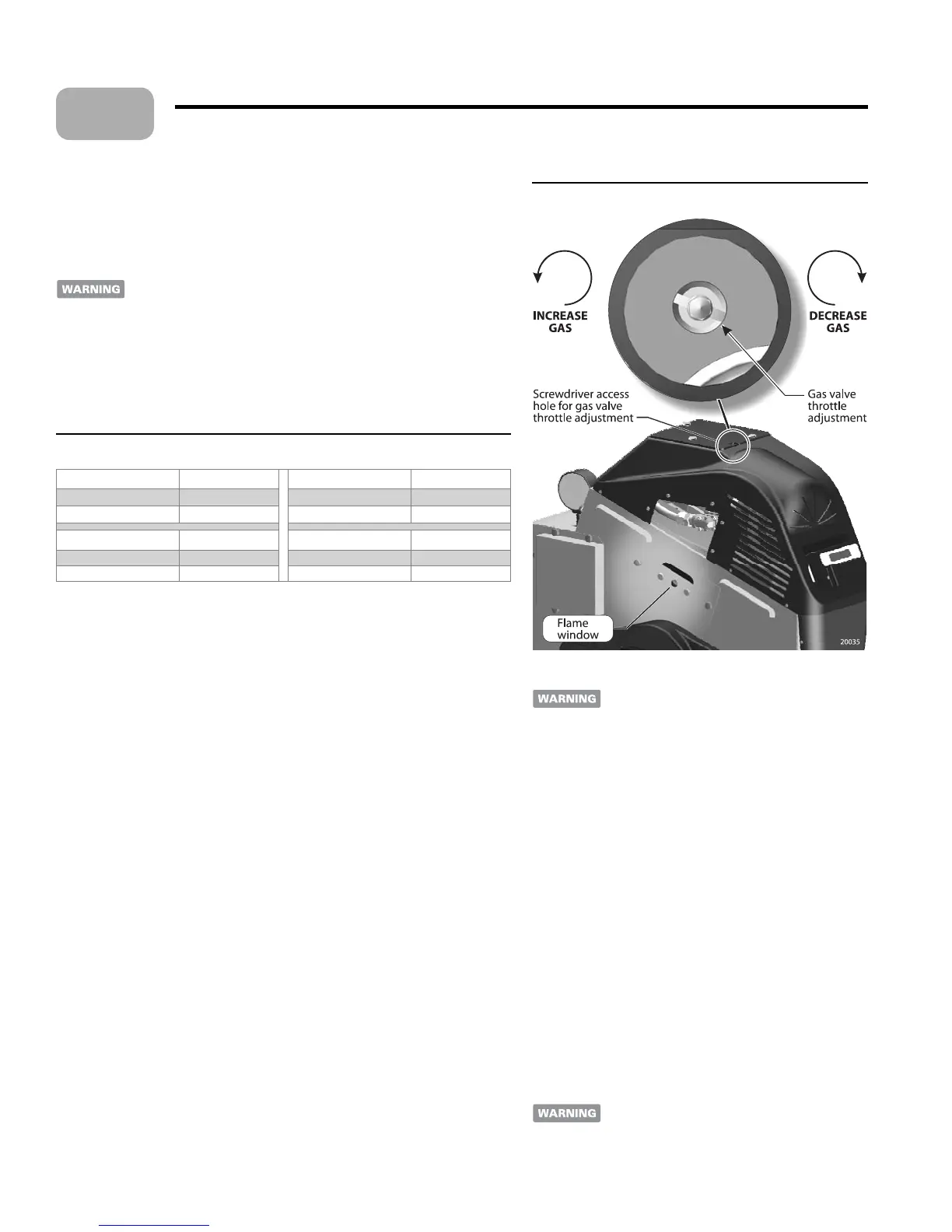
Figure 29 Throttle adjustment and ame window
Adjust gas valve throttle setting
Allow combustion to stabilize
Allow the boiler to operate 15 minutes, or as needed to obtain a steady reading on
the analyzer.
If the ame or burner surface appear red, NO NOT allow the boiler
to run without adjusting the gas valve thro le to reduce fuel input as
described below. Proceed with nal thro le se ing only if the ame is
visually acceptable (blue and steady).
Acceptable CO
2
/O
2
values
e CO
2
/O
2
values must be within the limits given in Table 5. e ame must be
blue and steady as discussed on page 37. CO must be no higher than 50 ppm.
Table 5 Acceptable CO
2
and O
2
values
Natural gas – High re CO
2
/ O
2
Natural gas – Low re CO
2
/ O
2
Minimum % 8.4 / 6.2 Minimum % 7.5 / 7.8
Maximum % 9.5 / 4.2 Maximum % 8.2 / 6.5
Propane – High re CO
2
/ O
2
Propane – Low re CO
2
/ O
2
Minimum % 9.3 / 6.2 Minimum % 8.2 / 7.8
Maximum % 10.7 / 4.2 Maximum % 9.1 / 6.5
Adjusting gas input with throttle screw - max input
Adjust gas input with the thro le screw adjustment using a long-shank common
bit screwdriver inserted through the hole in the jacket top. (Figure 29)
When adjusting the thro le se ing, make changes in half-turn increments. Allow
the ame to stabilize before adjusting each time. (Reduce gas input if the ame or
burner appears red.)
If CO
2
is too HIGH (O
2
too low):
REDUCE gas by turning the adjustment CLOCKWISE (one half turn at a
time). Recheck the analyzer and ame a er each half turn.
4. If CO
2
is too LOW (O
2
too high):
INCREASE gas by turning the adjustment COUNTERCLOCKWISE (one
half turn at a time). Recheck the analyzer and ame a er each half turn.
Verify gas inlet pressure
With the boiler operating at high re, check the gas pressure at the manual gas
valve. Gas pressure should never fall o by more than 2 inches w.c. (50 mm).
To meter gas input (natural gas only):
Meter gas input with the high- re jumper in place.
Turn o all other gas appliances that use the same gas meter as the boiler.
Call your gas supplier and ask for the heating value of the gas (Btu per cubic foot).
Start the boiler and let it run for 15 minutes (high- re jumper in place).
With the boiler operating, clock the time in
SECONDS that it takes to burn
10 cubic feet of gas at high re.
Insert the heating value and the time, in seconds, into the formula below.
Input = [
Gas Btu per cubic foot] x [3600] x [10] ÷ [seconds]
7. If the computed rate exceeds the desired input rate or 200,000 Btuh, reduce the gas
input with the gas thro le adjustment.
•
•
1.
2.
3.
•
•
1.
1.
2.
3.
4.
5.
6.
Starting the boiler (continued)
Never operate the boiler at an input higher than
its rating. Excess input can result in overheating
and damage to the heat exchanger and boiler
components.
Check low re operation.
Turn the boiler on/o switch OFF.
Remove the high- re contact jumper. Connect the jumper
wire across the low- re terminals of the connector board
(Figure 28, page 37). ese terminals are located on the
lower row as shown.
Turn the boiler on/o switch ON.
e boiler will start at about 30% of input and then move to
the low re condition.
Make sure the ame is blue and steady, NOT red or light
blue and unsteady.
If the ame or burner appears red, or if the CO
2
or O
2
are
outside the ranges of Table 5, turn the boiler on/o switch
OFF.
See the next page for instructions to adjust the gas valve
low- re se ing.
If ame and CO
2
/O
2
/CO are acceptable, proceed with set-
up (page 40) No further gas valve adjustments
are needed
. Replace the gas valve cover plate. Remove the
low- re jumper and replace the electrical panel cover.
Changing from propane to natural gas or
natural gas to propane
When adjusting
the boiler for a di erent gas, the low- re gas
adjustment must be changed using the procedure
on page 39.
1.
2.
3.
4.
5.
6.
7.
8.
12
 Loading...